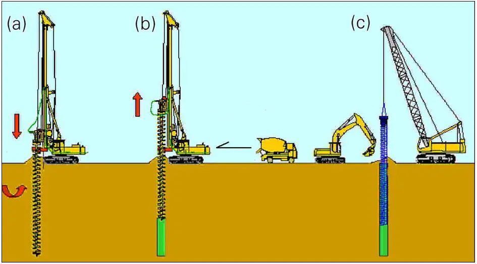
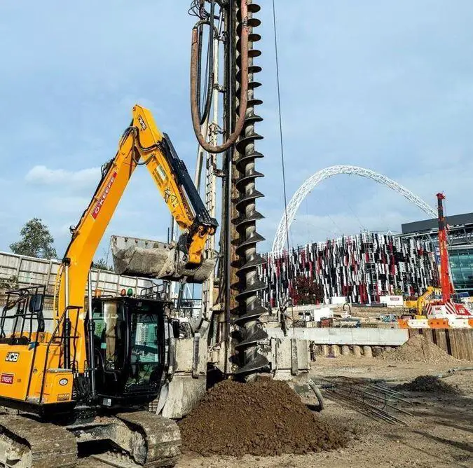
Continuous flight auger (CFA) piles are cast-in-situ replacement piles that are constructed by rotating and driving a hollow-stem continuous flight auger into the ground at a regulated speed to the desired pile depth.
As the auger is withdrawn, concrete is pumped into the borehole through the hollow stem of the auger under constant positive pressure. The reinforcing cage can be installed and driven to the desired depth into the freshly poured concrete once the auger has been completely removed from the borehole.
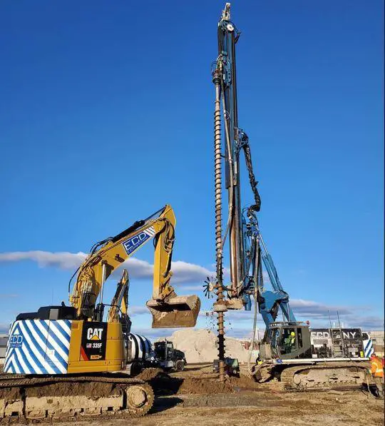
Continuous flight auger drilling belongs to the dry rotary drilling methods. Drilling fluids or temporary casings are not necessary because the hollow stem auger supports the excavated shaft continuously during the drilling process. Although CFA piles were first created to support locations with weak, sandy materials beneath the water table, their instrumentation control, low vibration, and depth/torque capacity have made them a very common foundation type today.
The possible range of diameters and depths for CFA piles has increased significantly since the development of high torque rotary heads and drilling rigs with extended masts, high crowd and extraction forces, and the ability to install CFA piles through a wide range of soil types, including clays, silts, peat, sand, and sandy gravels. With the help of innovative, automated control systems and the large crowd forces that modern drilling rigs can produce, it is feasible to construct CFA piles through hard soil layers and socket them into rock.
However, the method is most suitable for cohesive, non-granular soils:
- Undrained shear strength: cu > 15 kN/m2
- No boulder presence
Although longer piles have rarely been utilized, CFA piles are normally constructed with diameters ranging from 0.3 to 0.9 m (12 to 36 in.) and lengths up to 30 m (100 ft). Because less powerful rigs have historically been employed for commercial operations with these piles in the United States, the practice has often leaned toward smaller piles with diameters of 0.3 to 0.6 m (12 to 24 in.). In Europe, bigger diameters [up to 1.5 m (60 in.)] have been used.
The reinforcement cage of CFA piles is often confined to the upper 10 to 15 m (33 to 50 ft) of the pile for ease of installation and also due to the fact that in many cases, relatively low bending stresses are transferred below these depths. In some cases, full-length reinforcement is used, as is most common with drilled shaft foundations.
Continuous flight auger (CFA) piles can be installed as single piles or as part of a pile group. Single CFA piles are typically used for smaller structures, such as soundwalls or light poles. Pile groups are used for larger structures, such as bridges. The minimum centre-to-centre spacing between CFA piles is typically 2.5 to 4 times the diameter of the pile. However, 3 times the pile diameter spacing is commonly adopted in practice.
Construction Procedure for CFA Piles
The process of constructing CFA piles can be broken down into the following essential steps:
- Preparation of site and setting up the rig
- Drilling
- Concrete placement
- Reinforcement installation
Before starting to drill a CFA pile, a flat and stable work area must be created at the pile location to support the weight and pressure of the drilling rig. The piling positions must have been predetermined through pile setting out. The inclination of the working area should be level within 3%.
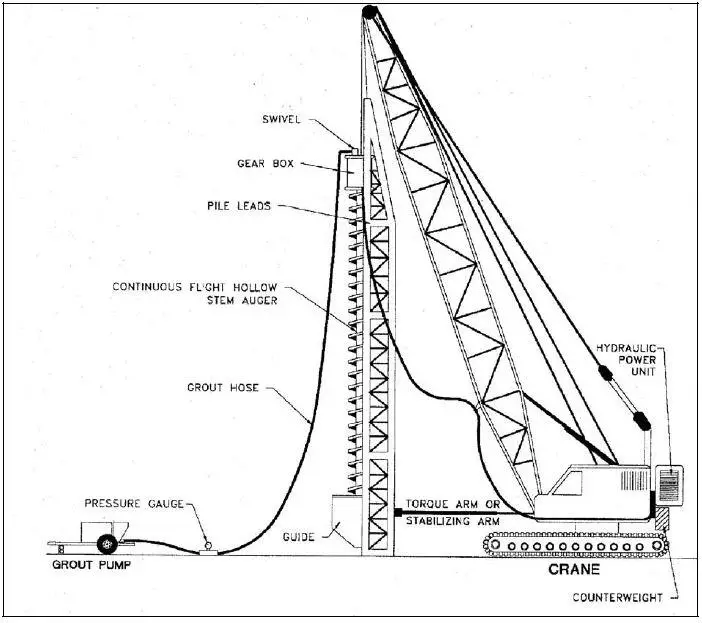
The drilling rig is positioned so that the tip of the CFA auger is exactly at the pile location. The mast of the drilling rig is then levelled using an automatic levelling device or any other equipment available to the contractor. The bottom end of the hollow auger shaft is sealed with a disposable tip.
Once the drilling rig is in place over the pile location, the CFA drill string is rotated into the ground to the desired depth using the torque from the drilling rig’s rotary drive and the crowd pressure from the crowd winch. If necessary, the drill string can be extended using Kelly extensions.
It is important to make sure that the auger does not rotate too quickly relative to its rate of penetration. If the auger rotates too quickly, it can remove soil from the sides of the borehole and bring it to the surface, which can weaken the friction interaction between the pile and the surrounding soil.
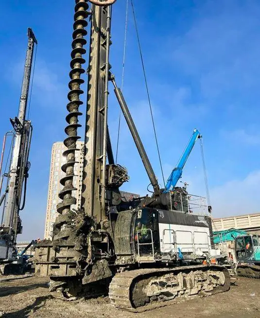
This is especially important when the auger encounters hard layers of soil or rock, as the penetration rate will be slower. The speed of rotation of the auger should be adjusted accordingly to ensure that the penetration rate is optimal.
Once the drilling rig reaches the desired depth, the concrete pump is turned on and concrete is pumped through the swan neck and swivel into the hollow shaft of the CFA auger. A pressure sensor on the swan neck measures the concrete pressure. Once the hollow shaft is full of concrete, the auger is extracted.
During the concreting and extraction phase, the auger is not normally rotated. However, some project specifications may allow for the auger to be rotated during extraction. In this case, it is important to make sure that the auger is rotated in the same direction as it was during drilling, to avoid disturbing the soil and contaminating the concrete.
In the CFA method, unlike other piling methods, the reinforcing cage is inserted into the borehole after it has been filled with concrete. Depending on the design, this cage can cover a portion of the pile’s depth or extend to the full depth of the pile. It is important to start the installation of the reinforcement cage immediately after pouring the concrete.
Typically, the reinforcing cage will naturally sink to depths of approximately 6 to 10 meters due to its weight, but for deeper depths, a vibrator is required to push the cage down to its intended position. In such cases, it is essential to weld the sections of the rebar cage together. A minimum concrete cover of 75mm is often adopted in piles.
Advantages and Limitations of CFA Piles
Continuous flight auger (CFA) piles have been used more often in private and commercial construction works than in transportation projects. There are several reasons for this trend. Some are related to the technology of CFA piles themselves, while others are due to institutional perceptions.
Favourable Geotechnical Conditions for CFA Piles
CFA piles generally work well in the following types of soil conditions:
• Medium to very stiff clay soils. In these soils, the shaft friction can provide the needed capacity within a depth of approximately 25 m (80 ft) below the ground surface. The major advantage of cohesive soils for CFA pile construction is that clays are generally stable during drilling and less subject to concerns about soil mining during drilling.
• Cemented sands or weak limestone. These soils are favourable if the materials do not contain layers that are too strong to be drilled using continuous flight augers. In cemented materials, it is not so critical that the cuttings on the auger maintain the stability of the hole. In addition, CFA piles can often produce excellent side-shear resistance in cemented materials because of the high side resistance created by the rough sidewall and good bond achieved using cast-in-place concrete.
• Residual soils. Residual soils, particularly silty or clayey soils that have a small amount of cohesion, are favourable for CFA pile installation because installation can be particularly fast and economical.
• Medium dense to dense silty sands and well-graded sands. These sands, even when containing some gravel, are commonly favourable. This is especially true if the groundwater table is deeper than the pile length.
• Rock overlain by stiff or cemented deposits. CFA piles can achieve significant end-bearing capacity on rock, provided that the overlying soil deposits are sufficiently competent to allow installation to the rock without excessive flighting. Flighting is the lifting of soil on the auger as the auger turns, in the manner of an Archimedes pump. Rock that is directly overlain by strong material or a transitional zone is well suited.
Static Capacity of CFA Piles
The static capacity of a CFA pile is somewhere between that of a drilled shaft and a driven pile. This is because the changes in lateral stress during installation are different for each type of pile. For CFA piles, the stresses in the soil remain similar to the pre-construction values (like a drilled shaft). For drilled displacement piles, the stresses in the surrounding soil increase (like a driven pile).
We can estimate the static capacity of CFA piles using methods developed for driven piles and drilled shafts, because their load-settlement behavior is similar. However, some methods have been developed specifically for CFA piles, and these methods are usually modifications of methods previously developed for drilled shafts or driven piles.
Similar to other types of deep foundations, the total axial compressive resistance (RT) of a CFA pile is calculated as the combination of the side-shear resistance (RS), and end-bearing resistance (RB):
RT = RS + RB
To calculate the shaft resistance, the pile length must first be divided into N pile segments. The side resistance of a particular pile segment “i” (of length Li, and diameter, Di) is obtained by multiplying the unit shaft friction resistance (fs,i sometimes referred to as load or transfer rate) of the segment by the surface area of the pile segment (π Di Li). The total shaft resistance is obtained by adding the contribution of all N pile segments as:
RS = ∑fs,i π Di Li
Some of the methods use an average unit side-shear (fs-ave) for the entire pile length, instead of summing individual pile segments. In these cases, the total side-shear resistance is calculated as:
RS = fs,aveπDL
where D is the average diameter of the pile, and L is the pile total embedment length.
The total end-bearing resistance (RB) is calculated as:
RB = qpAb
where qp is the unit end-bearing resistance, and Ab is the cross-sectional area of the pile at the base.
Conclusion
CFA piles are a versatile and widely used type of deep foundation that can be used in a variety of applications, including:
- Supporting heavily loaded structures, such as bridges, buildings, and towers
- Transmitting loads through soft or unstable soil layers
- Providing resistance to lateral loads, such as wind and seismic loads
CFA piles are constructed using a continuous flight auger (CFA) machine, which drills a hole into the ground after which concrete is poured into the hole. The CFA machine is equipped with a hollow auger that rotates and advances into the ground. When the embedment depth is reached, concrete is pumped down the hollow auger and into the hole as the auger is withdrawn.
The design of CFA piles is similar to the design of other types of deep foundations, such as drilled shafts and driven piles. The design process takes into account the load requirements, the soil conditions, and the specific characteristics of the CFA pile. Despite some inherent challenges challenges, CFA piles have become a popular choice for a wide range of projects due to their versatility, cost-effectiveness, and reliability.


What is the approximate cost of carrying out the whole installation process out in Nigeria?
Thank you, sir,
What is the allowable depth of a reinforcing cage for a 40m depth 750mm pile? That is, if I have my pile to be 40m, around what depth can my reinforcement get to, for me to be safe?