This should be a long post, but I am going to try and keep it as brief as possible. This post is more like an excerpt from the publication ‘Structural Analysis and Design of Residential Buildings using Staad Pro V8i, CSC Orion, and Manual calculations’. Here, we are going to briefly present some practical analysis and design of some reinforced concrete elements using Staad Pro software, Orion software, and manual calculations. Ultimately, we are going to make some comparisons of the results obtained based on the different methods adopted in the analysis and design. To learn how to model, design, and detail buildings from the scratch using Staad Pro, Orion, and manual methods, see the link at the end of this post.
To show how this is done, simplified architectural floor plans, elevations, and sections, for a residential two-storey building have been shown below for the purpose of structural analysis and design (see the pictures below).
The first step in the design of buildings is the preparation of the ‘general arrangement’, popularly called the G.A. The G.A. is a drawing that shows the disposition of the structural elements such as the slabs and their types, the floor beams, the columns, and their interaction at the floor level under consideration. For the architectural drawings above, the adopted G.A. is shown in Figure 7. below. There are no spelt out rules about how to prepare G.A. from architectural drawings, but there are basic guidelines that can guide someone on how to prepare a buildable and structurally efficient G.A.
Design data:
Fck = 25 N/mm2, Fyk = 460 N/mm2, Cnom (slabs) = 25mm, Cnom (beams and columns) = 35mm, Cnom (foundations) = 50mm
Thickness of slab = 150mm; Dimension of floor beams = 450mm x 230mm; Dimension of columns = (230 x 230mm)
DESIGN OF THE FLOOR SLABS
PANEL 1: MANUAL ANALYSIS
The floor slab (PANEL 1) is spanning in two directions since the ratio (k) of the longer side (Ly) to the shorter side (Lx) is less than 2.
Hence, k = Ly/Lx = 3.825/3.625 = 1.055 (say 1.1)
Moment coefficients (α) for two adjacent edges discontinuous (pick from table);
Short Span
Mid-span = 0.042
Continuous edge = 0.056
Long Span
Mid-span = 0.034
Continuous edge = 0.045
Design of short span
Mid span
M = αnLx2 = 0.042 × 10.9575 × 3.6252 = 6.0475 KN.m
MEd = 6.0475 KNm
Effective Depth (d) = h – Cc – ϕ/2
Assuming ϕ12mm bars will be employed for the construction
d = 150 – 25 – 6 = 119mm; b = 1000mm (designing per unit width)
k = MEd/(fckbd2 )
= (6.0475 × 10⁶)/(25 × 1000 × 1192 ) = 0.0171
Since k < 0.167 No compression reinforcement required
z = d[0.5+ √(0.25 – 0.882k)] = z = d[0.5+ √(0.25 – (0.882 × 0.0273)] = 0.95d
As1 = MEd/(0.87fyk z)
As1 = (6.0475 × 10⁶)/(0.87 × 460 × 0.95 × 119) = 133.668 mm2/m
Provide Y12mm @ 250mm c/c BOT (ASprov = 452 mm2/m)
A little consideration will show that this provided area of steel will satisfy serviceability limit state requirements. To see how to carry out deflections and crack control verifications, see the the link at the bottom of this post.
Result from Orion showing the Short Span (mid span) design moments (Wood and Armer effects inclusive) (PANEL 1)

Result from Staad showing the Short Span (mid span) design moments (Wood and Armer effects inclusive) (PANEL 1)
A little observation will show that the design moment values from the different methods are very similar. The full detailing of the floor slabs is as shown below.
Figure 9: Bottom Reinforcement Detailing
Figure 10: Top Reinforcement Detailing

Figure 11: Section of the floor slab
DESIGN OF THE BEAMS
Let us take Beam No 1 from our GA as a design case study:
The loading of the beam has been carried out as shown below. The beam is primarily subjected to load from the slab, the weight of wall, and its own self-weight. To see how to manually calculate the loading on beams, follow the link at the end of the post.
The internal forces from the loading is as shown below;
The internal forces from Orion software for Beam No 1 is as shown below. Load decomposition using finite element analysis was used for the load transfer.
The internal forces from Staad software for Beam No 1 is as shown below.

As1 = MEd/(0.87fykz)
= (36.66 × 10⁶)/(0.87 × 460 × 0.95 × 399) = 241.667 mm2
Provide 2Y16 mm BOT (ASprov = 402 mm2)
The detailing of Beam No 1 is as shown below;
DESIGN OF THE COLUMNS
Loads from slabs and beams are transferred to the foundations through the columns. In typical cases, columns are usually rectangular or circular in shape. Normally, they are usually classified as short or slender depending on their slenderness ratio, and this, in turn, influences their mode of failure. Columns are either subjected to axial, uniaxial, or biaxial loads depending on the location and/or loading condition. Eurocode 2 demands that we include the effects of imperfections in the structural design of columns. The design of columns is covered in section 5.8 of EC2.
The column axial loads have been obtained by summing up the reactions from all the beams supported by the columns, including the self weight of the column.
Let us use column A1 as example.
At the roof level, the column is supporting beam No 2 (Support Reaction V1 = 13.27 KN) and Beam No 3 (Support Reaction VA = 12.99 KN). At the first floor level (see Analysis and Design of Beam No 1 and 2), the column is supporting Beam No 1 (Support Reaction V1 = 41.38 KN), and Beam No 2 (Support Reaction VA = 42.49 KN). Therefore the summation of all these loads gives the axial load transferred from the beams. For intermediate supports, note that the summation of the shear forces at the support gives the total support reaction (neglect the signs and use absolute value. Another method of calculating Column Axial Load is by Tributary Area Method. This method has not been adopted in this work.
COLUMN A1
Total Columns Self weight = 12.14 KN
Load from roof beams = 13.27 + 12.99 = 26.26 KN
Load from floor beams = 46.21 + 42.49 = 88.70 KN
Total = 127.13 KN
Axial Load from Orion (A1) = 126.6 KN
Axial Load from Staad (A1) = 130.684 KN
COLUMN A3
Total Columns Self weight = 12.14 KN
Load from roof beams = 35.41 + 11.46 = 46.87 KN
Load from floor beams = 105.33 + 60.85 = 166.18 KN
Total = 225.19 KN
Axial Load from Orion (A3) = 202.3 KN
Axial Load from Staad (A3) = 201.632 KN
COLUMN A5
Total Columns Self weight = 12.14 KN
Load from roof beams = 17.19 + 5.70 = 22.89 KN
Load from floor beams = 83.64 + 37.91 = 121.55 KN
Total = 156.58 KN
Axial Load from Orion (A5) = 155.9 KN
Axial Load from Staad (A5) = 163.207 KN
COLUMN A7
Total Columns Self weight = 12.14 KN
Load from roof beams = 43.15 + 9.48 = 52.63 KN
Load from floor beams = 38.26 + 62.45 = 100.71 KN
Total = 165.48 KN
Axial Load from Orion (A7) = 133.9 KN
Axial Load from Staad (A7) = 140.392 KN
As you can see, for design purposes, the axial loads from the three methods are very comparable. To see how to obtain the column design moments from the use of sub-frames, follow the link at the end of the post.
Design of Column E5
Reading from chart; d2/h = 0.2;
MEd/(fck bh2 )
= (10.002 × 10⁶)/(25 × 230 × 2302 ) = 0.03288
NEd/(fckbh)
= (399.88 × 10³)/(25 ×230 × 230) = 0.302
From the chart:
(AsFyk)/(bhfck ) = 0.05
Area of longitudinal steel required (As) = (0.05 × 25 × 230 × 230)/460 = 143.75 mm2
As,min = 0.10 NEd/fyd
= (0.1 × 399.887)/400 = 0.099 mm2 < 0.002 × 230 × 230 = 105.8 mm2
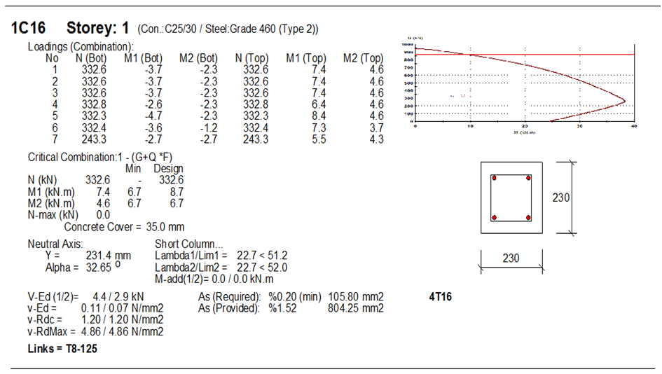
Provide 4Y16mm (Asprov = 804 mm2)
Links
Minimum size = 0.25ϕ = 0.25 × 16 = 4mm < 6mm
We are adopting Y8mm as links
Spacing adopted = 200mm less than min{b, h, 20ϕ, 400mm}
Result from Orion for column E5
Result from Staad for column E5
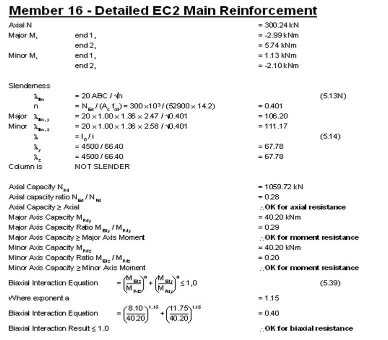

Staad Provided Y8@225mm links
The column detailing is as shown below;
DESIGN OF FOUNDATIONS
All loads from the superstructure of a building are transferred to the ground. If the foundation of a building is poorly designed, then all the efforts input in designing the superstructure is in vain. It is therefore imperative that adequate care is taken in the design of foundations. Foundation design starts with a detailed field and soil investigation. It is very important to know the index and geotechnical properties of the soil, including the soil chemistry, so that the performance of the foundation can be guaranteed.
Analysis and Design of footing E8
Bearing Capacity of the foundation = 150 KN/m2;
Effective depth
Concrete cover = 50mm
AssumingY12mm bars,
d = 400 – 50 – 6 = 344mm
The ultimate limit state design moment can be obtained by considering the figure below;
k = MEd/(fck bd2)
= (37.518 × 10⁶)/(25 × 1000 × 3442 ) = 0.01268 (designing per metre strip)
Since k < 0.167 No compression reinforcement required
z = d[0.5+ √(0.25 – 0.882k)] = z = d[0.5+ √(0.25 – (0.882 × 0.0273)] = 0.95d
As1 = MEd/(0.87fykz)
= (37.518 × 10⁶)/(0.87 × 460 × 0.95 × 344) = 286.869 mm2/m
To calculate the minimum area of steel required;
fctm = 0.3 × (fck)(2⁄3) = 0.3 × 25 (2⁄3) = 2.5649 N/mm2 (Table 3.1 EC2)
ASmin = 0.26 × fctm/Fyk × b × d = 0.26 × 2.5649/460 ×1000 × 344 = 498.7 mm2
Check if ASmin < 0.0013 × b × d (447.2 mm2)
Since, ASmin = 498.7 mm2, the provided reinforcement is adequate.
Provide Y12 @ 200mm c/c (ASprov = 565 mm2/m) each way
Shear at the column face
Ultimate Load on footing from column = 399.887 kN
Design shear stress at the column perimeter vEd = βVEd/(u0d)
β is the eccentricity factor (see section 6.4.3 of EC2)
β = 1+ 1.8√[(16.48/230)2+(8.99/230)2] = 1.146
Where uo is the column perimeter and d is the effective depth
vEd = βVEd/(u0d)
= (1.15 × 399.887 × 103)/(4(230) × 344) = 1.452N/mm2
VRd,max = 0.5vfcd
v = 0.6[1 – (fck/250) ] = 0.6[1 – (25/250) ] = 0.54 N/mm2
fcd = (αcc fck)/γc = (0.85 × 25)/1.5 = 14.167 N/mm2
VRd,max = 0.5 × 0.54 × 14.167 = 3.825 N/mm2vEd < VRd,max. This is very ok
Transverse shear at ‘d’ from the face of column
Width of shaded area = a – d = 0.635 – 0.344 = 0.291m
Area of shaded area = (1.5m × 0.291m) = 0.4365 m2
Therefore, ΔVEd = (189.386 + 175.939)/2 × 0.4365 m2 = 79.077 KN
vEd = VEd/bd = (79.077 × 10³)/(1500 × 344) = 0.15325 N/mm2
VRd,c = [CRd,c k (100ρ1 fck )(1/3) + k1.σcp] × (2d/a) ≥ (Vmin + k1.σ,sub>cp) bw.d
CRd,c = 0.18/γc = 0.18/1.5 = 0.12
k = 1 + √(200/d) = 1+√(200/344) = 1.7624 > 2.0, therefore, k = 1.7624
Vmin = 0.035k(3/2) fck(1/2)
Vmin = 0.035 × (1.7624)(3/2) × (25)(1/2) = 0.4094 N/mm2
ρ1 = As/bd = 565/(1000 × 344) = 0.001642 < 0.02;
VRd,c = [0.12 × 1.7624 (100 × 0.001642 ×25 )(1/3) ] = 0.3386 N/mm2 × (2d/a) < Vmin
But in this case, d = a
Hence, VRd,c = 2 × 0.3386 = 0.6772 N/mm2
Since VRd,c (0.6772) > VEd (0.1503 KN), No shear reinforcement is required.
Punching Shear at 2d from the face of column
Punching shear lies outside the footing dimensions. No further check required.
Design Result from Orion
The detailing of the footing is as shown below;
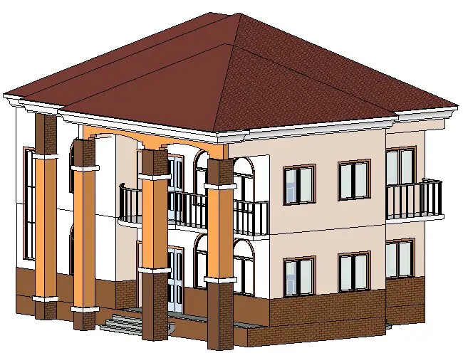
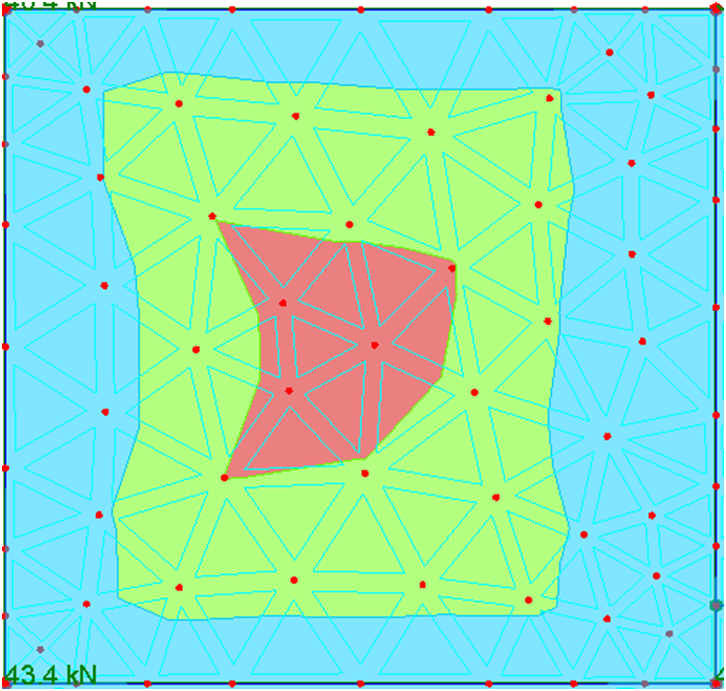
The structural analysis and design of all members have been fully done, including a step by step tutorial on how to model and design on Orion and Staad Pro, and how to manually design. See the completed models below;
To download the simplified e-book where all the members have been designed and completely detailed, including bar bending schedule and quantification of materials, click HERE.
Thank you, and God bless you.






Well done sir
What is c nom
Nominal cover to reinforcement (concrete cover)
In short God Bless you my able Engr., I really love your effort and I also pray for myself to have a such zeal to help other like this.
Thank you very much… We will keep working hard
your have great zeal ….i wish you goodlucky in future….how can i get your practical book…..
my broda God bless u. u r doing a great work, d lord is ur strength.
Amen… Thank you bro
You have done well….. How can I purchase that book…
thanks engineer Ubani and this is a big effort i hope to you full successful in your life
Regards..
Well-done sir, but I can't find any link in the end
Sir I finished in a school were by we cram to pass now am a graduate what will I show for outside I really need to be good at something
You now have to discover yourself based on what you really want, and give your all towards getting it.
good job, but one thing still unclear, how did you arrive at 12.147KN has column self weight?? by my calculation its 0.23*0.23*3*24=3.8KN
Multiply by the column hieght
Nice Content ..
Great job!! ?
God bless you Sir. U did it all .
Thanks for this straight forward analysis,but sir how can someone load a Column of more than 2 floors
Great Job.
Thank You Sir
Super-Duper site! I am Loving it!! Will come back again, Im taking your feed also, Thanks.
In addition, the load requirements, fixtures, and even materials will vary significantly between commercial and residential roofs. For example, commercial roofs must have a larger load-bearing capacity than residential roofs often just because of the materials involved in their construction.
pls i need a mentor like you …weldone engineer
Nice One Engineer, I grabbed alot..Job well Done.
This blog happens to be one of the best blog on the topic.It is just a proper critique blog, would suggest others it as well. You have done an excellent job with this content I must say. I love your posts always.
Such a wonderful article upon the structural analysis and design of residential building who is using staad pro orion and manual calculation.I enjoyed reading this article as it provided us lots of information regarding it. I am sure many people will come to read more about it in future.
Great analysis, I love how you really went in-depth with everything it really projects what one needs to know about structural analysis and design of residential buildings using staad-pro orion and-manual calculations. You have done an excellent job with this content I must say.
Wonderful information on structural analysis and design of residential buildings using staad pro orion and manual calculations, thanks a lot for sharing kind of content with us. Your blog gives the best and the most interesting information. I wonder if we can gather such practical information about it, a great post definitely to come across.
Thank you very much for presenting this data about structural analysis and design of residential buildings using staad pro orion and manual calculations, it’s known how to get approved but what are the next steps after getting the approval… Wonderful information, thanks a lot for sharing kind of content with us… great post!
Hi, thank you for such a brilliant post. I have been reading some blogs that gives me more knowledge about structural analysis and design of residential buildings using staad pro orion and manual calculation. I must say this is one of the best among them. You have done a great research for I feel, thanks for sharing.
It’s a great source of knowledge; I think it will be helpful for lot of people who are looking for learning more about the structural analysis and design of residential buildings using staad pro orion and manual calculations. Thank you very much for sharing this article.I have also found this resource useful and its related to what you are mentioning.
Here we get to know about modern structural analysis and design of residential buildings using staad pro orion and manual calculations. information in detail. It helps us to decide that which one is best among its types. I enjoyed reading this article and would suggest others it as well. Thank you for this article! This is really very informative for us.
NICE CONTENT….
GOOD WORK
God bless you for sharing, its of great value to us.
I calculated my soil pressure as follow:
soil pressure = 1.5 x total load coming on the column/area of footing
= 1.5 x (39.9887+ 399.887)/(1.5 x 1.5)
= (1.5 x 439.8757)/2.25
= 659.81355/2.25
= 293 kN/m2
instead of 189.386 kN/m2.
Please enlighten us on this condition.
Thanks waiting for your reply.
Where did you get the 1.5 factor from?
Factor of safety I guess
This article gives detail about structural analysis and design of residential buildings using staad pro orion and manual calculations and this article shared so much information regarding the same… I enjoyed reading while going through this article and this is the best link for gaining all the information about it.
One of the nice document you have made about structural design. I really like this one. Thanks for sharing with us.
God bless you for this great work. more blessings
Nice work. How can one extract design information/calculations from Orio.
Thank you for taking time to educate especially our elite who always run away from detail building drawings and do short cut at their own perils.
Engr Ubani, Great work! My only comment is that you loaded all spans with max load. I think it is necessary to do a critical load arrangement on the continous beam where the longer span is loaded with max load and short span with minimum load. This will result in larger hogging moment in the midspan of the short span. This will also help in drawing a proper BM envelope for the beam and guide in the placement of reinforcement. Clearly, the main reinforcement will be placed at the top of the mid span for the short span while main reinforcement for the longer span will be placed at the bottom.
I am still trying to get this calculation
Is it possible for people from other countries to access your material?
Thanks from the bottom of my heart brother.
I just need the table using to calculate the moment
We’re is the link of this post, I need to see the manual calculation of the beam
Do you have a guide on the rules of slab detailing………..am not sure how you go the top reinforcement??
Find the link to detailing of RC slabs below;
https://structville.com/2021/05/detailing-of-reinforced-concrete-slabs.html
Please how do i get access to purchased document?