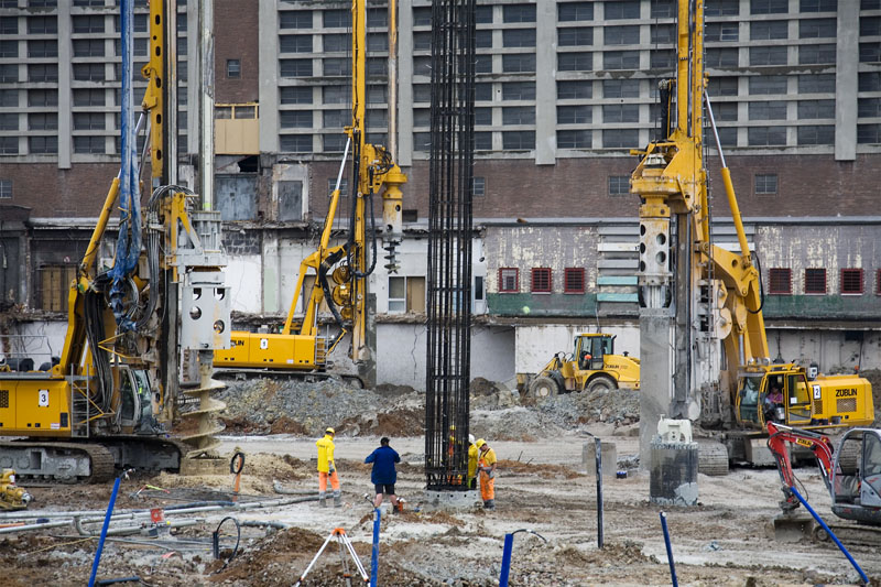
Precast piles are designed to withstand stresses caused during their installation, and the load from their service life. Bored piles on the other hand and usually designed to withstand the stresses they are subjected to while supporting the superstructure and other actions as may be anticipated. These could be earthquake forces, other lateral loads, or uplift forces.
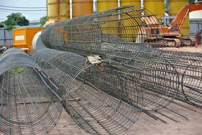
Furthermore, piles of all types may be subjected to bending stresses caused by eccentric loading, either as a designed loading condition or as a result of the pile heads deviating from their intended positions. This post is aimed at exploring the methods of providing longitudinal reinforcement for bored piles, and the minimum reinforcement acceptable.
Buckling of piles that are embedded in a firm soil cannot occur unless they are loaded beyond their capacity, hence there is no need to design such piles as slender columns. However, when the piles are projecting above the ground level, then there is a need to consider such behaviour.
Also, when a pile passes through a very weak stratum of clay with low lateral stiffness, and is founded on a hard stratum, then buckling becomes a problem. If the undrained shear strength of the soil cu is less than 10 kN/m2, then there is a need to check for buckling.
Read Also….
Structural design of pile caps using strut and tie model
Design of piles in sand: Case Study of Lekki Pennisula Lagos
Reinforcement Requirement and Detailing of Bored Piles
Section 9.8.5 of EN 1992-1-1:2004 deals with the detailing requirements of bored piles. Clause 9.8.5(3) said that bored piles with a diameter not exceeding 600mm should be provided with a minimum longitudinal reinforcement of As,bpmin. The recommended minimum longitudinal reinforcement of cast-in-place bored piles is given in Table 9.6N of EN 1992-1-1:2004 and reproduced below;
The requirement further states that the minimum diameter for the longitudinal bars should not be less than 16 mm. Piles should have at least 6 longitudinal bars and the clear distance between bars should not exceed 200 mm measured along the periphery of the pile.
However, these rules differ from the requirements of BS EN 1536:2010 + A1(2015) which states that for reinforced piles, the minimum longitudinal reinforcement shall be 4 bars of 12 mm diameter, and the spacing should be maximised to allow proper flow of concrete but should not exceed 400 mm.
According to clause 6.9.2.1 of BS 8004:2015, the design compressive resistance (Rc,d) of the reinforced length of a cast-in-place pile is given by;
Rc,d = fcdAc,d + fydAs,d
Where;
fcd = design compressive strength of the concrete = (αcc × fck)/(kf × γc)
αcc = factor taking into account the long-term reduction in strength of concrete (take as 0.85)
fck = characteristic compressive strength of concrete
kf = A multiplier to the partial factor of concrete for concrete piles cast-in-place without permanent casing (value is 1.1)
γc = partial factor for concrete
Ac,d = cross-sectional area of pile
fyd = design yield strength of steel = (fyk / γs)
fyk = characteristic yield strength of steel
γc = partial factor for steel
As,d = Area of steel required
The links, hoops, or helical reinforcements are required to be designed in accordance with EC2, but the diameter of the bar should not be less than 6 mm, or one-quarter of the maximum diameter of the longitudinal bars. The maximum reinforcement should be taken as 4% of the cross-sectional area.
According to clause 6.9.2.6, of BS 8004:2015, depending on the magnitude of loading, a cast-in-situ pile may be reinforced over its whole length, over part of its length, or merely provided with short splice bars at the top for bonding into the pile cap. If the concrete pile is expected to resist tensile forces, the reinforcement should be extended down to the full length.
Solved Example
A 500 mm diameter pile has a safe working load of 540 kN and the actual load it is being subjected to is 485 kN. Provide suitable reinforcement for the pile if it is a frictional pile embedded in dense sand and the characteristic strength of concrete and steel are 30 MPa and 500 MPa respectively.
Solution
Rc,d = fcdAc,d + fydAs,d
Ac,d = πd2/4 = (π × 5002)/4 = 196349.54 mm2
fcd = (0.85 × 30)/(1.1 × 1.5) = 15.45 N/mm2
fyd = (500 / 1.15) = 434.782 N/mm2
Rc,d = 540000 N
540000 = (196349.54 × 15.45) + 434.782 As,d
A little consideration will show that solving for As,d will give us a negative value, therefore provide minimum reinforcement
Since Ac < 0.5 m2;
As,bpmin = 0.005 × Ac,d = 0.005 × 196349.54 = 982 mm2
Provide 6H16mm (As,prov = 1206 mm2)
Following strictly the detailing requirements of EC 2, a clear distance of 200 mm has not been exceeded.
Provide H10mm @ 300mm pitch spiral links
Read Also;
How to Apply Load Model 1 on Highway Bridges
Analysis of Trusses Using Direct Stiffness Method
Minimum Concrete covers (clause 7.6.4 BS 8004:2015)
60mm for piles with diameter > 600mm
50mm for piles with diameter ≤ 600 mm
The cover can be increased to 75mm under special circumstances.
Thank you for visiting Structville Today… God bless you


In accordance with British Standard, all cover for concrete cast against the ground, i.e. for each and every pile, is 75mm
Nice one sir
Nice one sir
How to calculate the shear link
good job! weldone
Good day engr
Pls I need comprehensive step, simple explatory on design of culvert according bs code
Thanks
please i need reference for minimum length of longitudinal bar length (where one-third is stated