Durability and strength are the two main types of limit states relevant to the design of masonry structures and masonry walls. The selection of masonry units and mortars for certain construction types and exposure classes is a key component of design for durability. The compressive strength of the masonry fd, is determined by;
fd = fk/γM
where;
fk is the characteristic compressive strength of masonry
γM is the partial factor for materials.
The following product/material characteristics affect the characteristic compressive strength of masonry:
• Group number of masonry unit
• Normalised mean compressive strength of masonry unit
• Compressive strength of the mortar.
The partial factor for materials is a function of the following aspects:
• Category of (masonry unit) manufacturing control
• Class of execution control.
In Europe, a wide range of masonry units are used. Numerous characteristics of the units vary, including the percentage, size, and orientation of voids or perforations, as well as the thickness of webs and shells. Therefore, the EN 1996-1-1:2004 (EC 6) drafting panel had to come up with strategies that would enable the usage of the vast majority of masonry materials that are currently offered in Europe. Producing European specifications for popular masonry unit types was how the process was really developed:
- clay
- calcium silicate
- aggregate concrete (sandcrete blocks)
- autoclaved aerated concrete
- manufactured stone and
- natural stone.
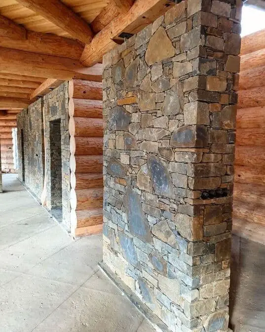
Each of the product properties in these requirements is backed by an appropriate test method using a declaration system. The superior structural use masonry units are put in Group 1, and the remaining masonry units are divided into Groups 2, 3, and 4, according to the product characteristics. Group 1 units typically contain no more than 25% void space. Between 25 and 55% of Group 2 clay and calcium silicate units are voids, while 25 to 60% of Group 2 aggregate concrete units are voided.
Normalised Compressive Strength of Masonry
The compressive strength of masonry units had to be normalised because to variations in unit sizes that are available throughout Europe and in testing methods. The compressive strength is converted to the air-dried compressive strength of an identical 100 mm wide 100 mm high unit of the same material to provide the normalised compressive strength, or fb.
The masonry’s normalised compressive strengths, fb, are given by;
fb = conditioning factor × shape factor × declared mean compressive strength
Compressive Strength of Mortar
Table 1 below lists the masonry mortar mixtures that the UK recommends using to reach the required strength specified in EC 6. Since the selection and designation of masonry mortars in EC 6 and BS 5628 are identical, similar mortars may be specified for a certain application or exposure.
Masonry mortars may be described by their compressive strength, which is indicated as the letter M followed by the compressive strength in N/mm2, for example, M4, or by their mix proportion, for example, 1:1:6, which denotes the cement-lime-sand proportions by volume. The latter, however, has the advantage of producing mortars that are known to be durable and should generally be employed in practise.
| Compressive Strength | Cement-lime-sand with or without air-entrainment | Cement-sand with or without air-entrainment | Masonry cement-sand | Masonry cement-sand | Mortar designation |
| M12 | 1:0 to 1/4:3 | – | – | (i) | |
| M6 | 1:1/2:4 to 4.5 | 1:3 to 4 | 1:2.5 to 3.5 | 1:3 | (ii) |
| M4 | 1:1:5 to 6 | 1:5 to 6 | 1:4 to 5 | 1:3.5 to 4 | (iii) |
| M2 | 1:2:8 to 9 | 1:7 to 8 | 1:5.5 to 6.5 | 1:4.5 | (iv) |
Unit Manufacturing Control
According to the manufacturing control, units produced in compliance with European criteria can also be divided into Category I or Category II. Category I units are those when the manufacturer employs a quality-control programme and there is a less than 5% chance that the units will not achieve the specified compressive strength. Masonry units rated as Category II are not meant to meet the Category I degree of trust. The category of the masonry unit delivered must be declared by the manufacturer.
Class of Execution Control
EC 6 permits up to five classes of execution control, but, like BS 5628, the UK National Annex only uses two classes, namely 1 and 2. The requirements for workmanship in EN 1996: Part 2 (EC 6-2), including adequate supervision and inspection, shall be followed whenever the work is performed, in accordance with Table 1 of the National Annex, and in addition:
(a) The specification, supervision, and control ensure that the construction is compatible with the use of the appropriate safety factors specified in EC 6;
(b) the mortar complies with BS EN 998-2, if it is manufactured in a factory, or if it is site-mixed, preliminary compressive strength tests conducted on the mortar to be used, in accordance with BS EN 1015-2 and BS EN 1015-11, indicate conformity to the strength requirements specified in EC 6.
Every time the work is completed in accordance with the craftsmanship guidelines in EC 6-2, including the necessary supervision, class 2 execution control should be adopted. According to BS 5628, Class 1 execution control is equivalent to the “special” category of construction control, whereas Class 2 is equivalent to the “regular” category.
Characteristic Compressive Strength of Masonry
The characteristic compressive strength of unreinforced masonry, fk, built with general-purpose mortar can be determined using the following expression
fk = Kfb0.7fm0.3
where;
fm is the compressive strength of general-purpose mortar but not exceeding 20 N/mm2 or 2fb, whichever is the smaller
fb is the normalised compressive strength of the masonry units
K is a constant obtained from the Table below (Table 4 of the UK Annex to EC6).
| Masonry Unit | Group | Values of K for general-purpose mortar |
| Clay | Group 1 Group 2 | 0.50 0.40 |
| Calcium Silicate | Group 1 Group 2 | 0.50 0.40 |
| Aggregate Concrete | Group 1 Group 1 (units laid flat) Group 2 | 0.55 0.50 0.52 |
Partial Factor for Materials (γM)
The values of the material property partial factors for the ultimate limit state listed in Table 1 of the National Annex to EC 6 are shown in Table 3. As is evident, they essentially depend on the type of unit, the type of execution control, and the level of stress.
| Class of execution control 1 | Class of execution control 2 | |
| When in a state of direct or flexural compression Unreinforced masonry made with: units of category I units of category II | 2.3 2.6 | 2.7 3.0 |
| When in a state of flexural tension units of category I and II | 2.3 | 2.7 |
Design of unreinforced masonry walls subjected to vertical loading
Having discussed the basics, the following outlines EC 6 rules for the design of vertically loaded walls as set out in section 6.1. The approach is very similar to that in BS 5628 and principally involves checking that the design value of the vertical load, NEd, is less than or equal to the design value of the vertical resistance of the wall, NRd, i.e.
NEd ≤ NRd
According to clause 6.1.2.1 of EC 6, the design vertical load resistance of a single leaf unreinforced masonry wall per unit length, NRd, is given by;
NRd = Φi,m tfk/γM
where;
Φi,m is the capacity reduction factor, Φi or Φm, as appropriate
t is the thickness of the wall
fk is the characteristic compressive strength of masonry
γM is the material factor of safety for masonry determined from Table 3.
Effective Height of Masonry Wall
The effective wall height is a function of the actual wall height, h, and end/edge restraints. It can be taken as;
hef = ρnh
ρn is a reduction factor where n = 2, 3 or 4 depending on the number of restrained and stiffened edges. Thus, n = 2 for walls restrained at the top and bottom only, n = 3 for walls restrained top and bottom and stiffened on one vertical edge with the other vertical edge free and n = 4 for walls restrained top.
Worked Example on Masonry wall panel design
In accordance with EN1996-1-1:2005 + A1:2012 incorporating Corrigenda February 2006 and July 2009 and the UK national annex
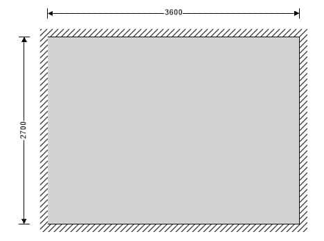
Masonry panel details
Unreinforced masonry wall without openings
Panel length; L = 3600 mm
Panel height; h = 2700 mm
Panel support conditions: All edges supported
Effective height of masonry walls
Reduction factor; ρ2 = 1.000
ρ4 = ρ2 / (1 + [ρ2 × h/L]2) = 0.640
Effective height of wall – eq 5.2; hef = ρ4 × h = 1728 mm
Single-leaf wall construction details
Wall thickness; t = 150 mm
Effective thickness; tef = t = 150 mm
Masonry details
Masonry type; Aggregate concrete – Group 2
Compressive strength of masonry; fc = 2.9 N/mm2
Height of unit; hu = 225 mm
Width of unit; wu = 150 mm
Conditioning factor; k = 1.0 – Conditioning to the air dry condition in accordance with cl.7.3.2
Shape factor – Table A.1; dsf = 1.3
Norm. mean compressive strength of masonry; fb = fc × k × dsf = 3.77 N/mm2
Density of masonry; γ = 18 kN/m3
Mortar type; M2 – General purpose mortar
Compressive strength of masonry mortar; fm = 2 N/mm2
Compressive strength factor – Table NA.4; K = 0.70
Characteristic compressive strength of masonry – eq 3.1
fk = K × fb0.7 × fm0.3 = 2.182 N/mm2
Characteristic flexural strength of masonry having a plane of failure parallel to the bed joints – Table NA.6
fxk1 = 0.167 N/mm2
Characteristic flexural strength of masonry having a plane of failure perpendicular to the bed joints – Table NA.6
fxk2 = 0.338 N/mm2
Lateral loading details
Characteristic wind load on panel; Wk = 0.700 kN/m2
Vertical loading details
Permanent load on top of wall; Gk = 21 kN/m;
Variable load on top of wall; Qk = 7 kN/m;
Partial factors for material strength
Category of manufacturing control; Category II
Class of execution control; Class 2
Partial factor for masonry in compressive flexure; γMc = 3.00
Partial factor for masonry in tensile flexure; γMt = 2.70
Partial factor for masonry in shear; γMv = 2.50
Slenderness ratio of masonry walls
Allowable slenderness ratio;SRall = 27
Slenderness ratio; SR = hef / tef = 11.5
PASS – Slenderness ratio is less than maximum allowable
Partial safety factors for design loads
Partial safety factor for permanent load; γfG = 1.35
Partial safety factor for variable imposed load; γfQ = 1.5
Partial safety factor for variable wind load; γfW = 0.75
Reduction factor for slenderness and eccentricity – Section 6.1.2.2
Vertical load at top of wall; Nid = γfGGk + γfQQk = 38.85 kN/m
Moment at top of wall due to vertical load; Mid = γfGGkeG + γfQQkeQ = 0 kNm/m
Initial eccentricity – cl.5.5.1.1; einit = hef / 450 = 3.8 mm
Moment at top of wall due to horizontal load; MEid = 0 kNm/m
Eccentricity at top of wall due to horizontal load; eh = 0 mm
Eccentricity at top of wall – eq.6.5;
ei = max(Mid / Nid + eh + einit, 0.05t) = 7.5 mm
Reduction factor at top of wall – eq.6.4;
Φi = max(1 – 2ei/t, 0) = 0.9
Vertical load at middle of wall;
Nmd = γfG(Gk + γth/2) + γfQQk = 43.771 kN/m
Moment at middle of wall due to vertical load;
Mmd = γfGGkeG + γfQQkeQ = 0 kNm/m
Moment at middle of wall due to horizontal load; MEmd = 0.087 kNm/m
Eccentricity at middle of wall due to horizontal load; ehm = MEmd / Nmd = 2 mm
Eccentricity at middle of wall due to loads – eq.6.7; em = Mmd / Nmd + ehm + einit = 5.8 mm
Eccentricity at middle of wall due to creep; ek = 0 mm
Eccentricity at middle of wall – eq.6.6; emk = max(em + ek, 0.05t) = 7.5 mm
From eq.G.2; A1 = 1 – 2 × emk/t = 0.9
Short-term secant modulus of elasticity factor; KE = 1000
Modulus of elasticity – cl.3.7.2; E = KE × fk = 2182 N/mm2
Slenderness – eq.G.4; λ = (hef / tef) × √(fk / E) = 0.364
From eq.G.3; u = (λ – 0.063) / (0.73 – 1.17emk/t) = 0.449
Reduction factor at middle of wall – eq.G.1;
Φm = max(A1 × ee-(u × u)/2, 0) = 0.814
Reduction factor for slenderness and eccentricity;
Φ = min(Fi, Fm) = 0.814
Verification of unreinforced masonry walls subjected to mainly vertical loading – Section 6.1.2
Design value of the vertical load;
NEd = max(Nid, Nmd) = 43.771 kN/m
Design compressive strength of masonry;
fd = fk /γMc = 0.727 N/mm2
NRd = Φ × t × fd = 88.786 kN/m
PASS – Design vertical resistance exceeds applied design vertical load
Unreinforced masonry walls subjected to lateral loading
Partial safety factors for design loads
Partial safety factor for permanent load; γfG = 1
Partial safety factor for variable imposed load; γfQ = 0
Partial safety factor for variable wind load; γfW = 1.5
Limiting height and length to thickness ratios for walls under the serviceability limit state – Annex F
Length to thickness ratio; L/t = 24
Limiting height to thickness ratio – Figure F.1; 80
Height to thickness ratio; h/t = 18
PASS – Limiting height to thickness ratio is not exceeded
Design moments of resistance in panels
Self-weight at middle of wall;
Swt = 0.5 × h × t × γ = 3.645 kN/m
Design compressive strength of masonry;
fd = fk/γMc = 0.727 N/mm2
Design vertical compressive stress;
sd = min(γfG × (Gk + Swt) / t, 0.15Ffd) = 0.089 N/mm2
Design flexural strength of masonry parallel to bed joints
fxd1 = fxk1/γMt = 0.062 N/mm2
Apparent design flexural strength of masonry parallel to bed joints
fxd1,app = fxd1 + σd = 0.151 N/mm2
Design flexural strength of masonry perpendicular to bed joints
fxd2 = fxk2 /γMt = 0.125 N/mm2
Elastic section modulus of wall;
Z = t2/6 = 3750000 mm3/m
Moment of resistance parallel to bed joints – eq.6.15
MRd1 = fxd1,appZ = 0.564 kNm/m
Moment of resistance perpendicular to bed joints – eq.6.15
MRd2 = fxd2Z = 0.469 kNm/m
Design moment in panels
Orthogonal strength ratio; m = fxd1,app / fxd2 = 1.20
Using yield line analysis to calculate bending moment coefficient
Bending moment coefficient; α = 0.027
Design moment in wall; MEd = γfW × α × Wk × L2 = 0.367 kNm/m
PASS – Resistance moment exceeds design moment
Summary
| Allowable | Actual | Utilisation | ||
| Slenderness ratio; | 27 | 11.5 | 0.427 | PASS |
| Vertical loading on wall; | 88.786 kN/m | 43.771 kN/m | 0.493 | PASS |
| Height to thickness ratio; | 80.000 | 18.000 | 0.225 | PASS |
| Design moment to wall; | 0.469 kNm/m | 0.367 kNm/m | 0.782 | PASS |








Good work God bless you
Please sir if pictures would be added to each stage of solution for proper understanding we will appreciate
thanks
How to calculate moment at the middle of the wal due to horizontal load (0.087 kNm/m)