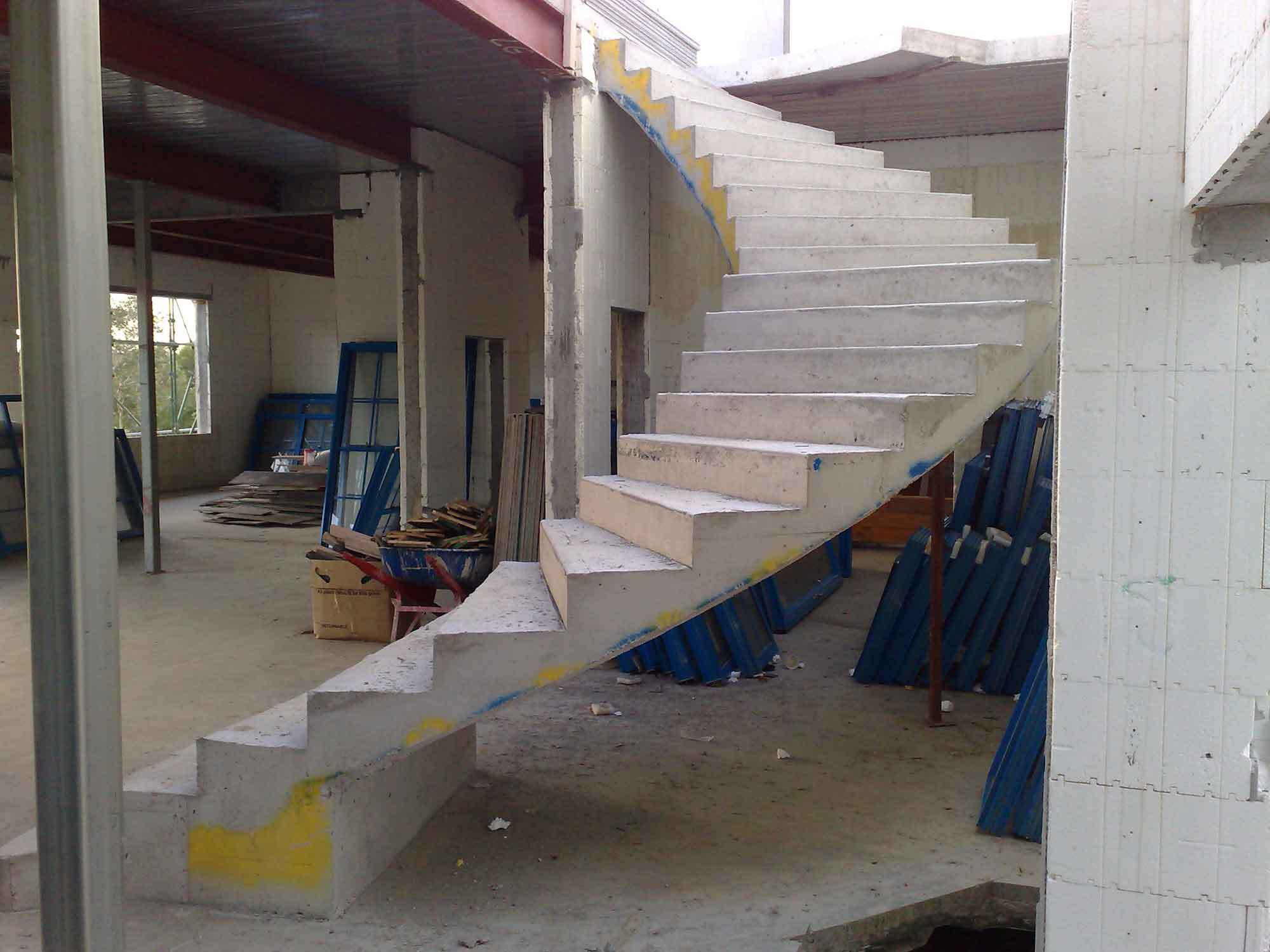
Helical staircases provide alternatives for vertical circulation in buildings. Due to their curved and elegant nature, they inspire awe and admiration whenever they are properly designed and constructed. The analysis and design of a helical staircase can be complex due to an inherent interaction of vertical moments, horizontal moments, vertical shear, lateral shear, axial force, and torsion. The complexity of helical staircases is due to their geometry.
Geometrically, a helical surface is a three-dimensional structure in space consisting of a warped surface that is generated by moving a straight line touching a helix so that the moving line is always perpendicular to the axis of the helix. In an oblique helix, the generating line always maintains a fixed angle with the helix. Since a helical staircase is a space member, all the six internal actions come into play at any section, having varying directions and lines of actions.
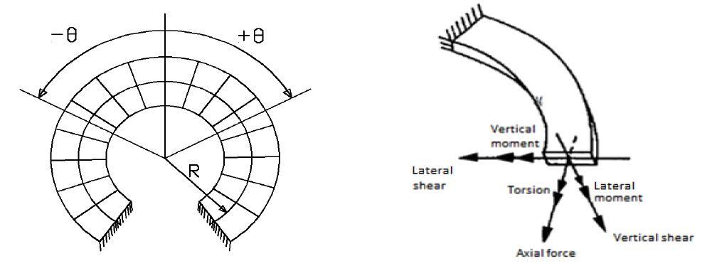
Despite the existence of the six internal stresses at any section in a helical staircase, they are usually designed for the horizontal bending moment only. Furthermore, helical staircases can sometimes be idealised as a fixed ended curved beam for the purposes of design due to their complexity.
Bergman (1956) proposed an approximate solution to helical staircases called the in-plane beam solution. The method reduces the problem to that of a horizontal bow girder, which fails to take into account the inherent structural strength of a helical beam.
Morgan (1960) and Scordelis (1960) presented the analysis of the longitudinal elastic axis of the helical beam as a three-dimensional structure indeterminate to the sixth degree. By selecting the redundant at mid-span and using the principle of symmetry, all but two of the redundants become zero. The two redundants at mid-span are the horizontal shear H and the vertical moment Mo.
Cusens and Trirojna (1964) carried out a test on half scaled fixed ended helical staircase and confirmed the equilibrium equations derived by Morgan. Santathadaporn and Cusens (1966) worked further on helicoidal stair slabs to simplify the design process. They proposed some simple equations for design purpose with the provision of using coefficients in the equations. They used computer program to solve those complicated equations and constructed a series of design charts to provide the values of the coefficients.
Reynolds and Steedman (1988) attempted further modifications of the charts provided by Santathadaporn and Cusens. The analytical approach they chose was the one made by Morgan and Scordelis. The proopsed equations and coefficients for determination of the internal stresses are as follows;
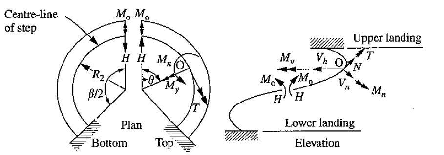
Horizontal moment Mn = Mo sinθsinϕ – HR2θtanϕcosθsinϕ – HR2sinθcosϕ + nR1sinϕ(R1sinθ – R2θ) —— (1)
Vertical moment My = Mocosθ + HR2θtanϕsinθ – nR12(1 – cosθ) —— (2)
Torsion T = (Mosinθ – HR2θcosθtanϕ + nR12sinθ – nR1R2θ)cosϕ + HR2sinθsinϕ —— (3)
Axial force N = -Hsinθcosϕ – nR1θsinϕ —— (4)
Vertical shear Vn = nR1θcosϕ – Hsinθsinϕ —— (5)
Radial horizontal shear Vh = Hcosθ —— (6)
Where;
Mo = Redundant moment acting tangentially at the midspan = k1nR22
H = Horizontal redundant force at midspan = k2nR2
Mvs = Vertical moment at supports= k3nR22
n = total design load on the staircase (kN/m2)
R1 = Radius of centreline of loading = 2(Ro3 – Ri3)/3(Ro2 – Ri2)
R2 = Radius of centreline of steps = 0.5(Ri + Ro)
θ = angle subtended in plan between point considered and mid-point of stair
ϕ = slope of tangent to helix centreline measured from horizontal
β = Total angle formed by the helical staircase in plan
k1 = GC/EI1
k2 = GC/EI2
I1, I2 = Second moment of area of stair section about horizontal axis and axis normal to slope respectively.
The 36 design charts presented by Santathadaporn and Cusens (1966) covered ranges of β of 60° to 720°, ϕ of 20° to 50°, b/h of 0.5 to 16 and R1/R2 of 1.0 to 1.1, based on a ratio of G/E of 3/7.
Four design charts are provided in Table 177 of (Reynolds and Steedman 10th Edition) and (Tables 2.90 and 2.91 of 11th Edition) for a ratio of G/E of 0.4 and by taking C to be one-half of the St. Venant value for plain concrete. These charts cover ranges of β of 30° to 360° and ϕ of 20° to 40°, with values of b/h of 5 and 10 and R1/R2 of 1.0 and 1.1, these being the ranges most frequently met in helical stair design. According to Reynolds and Steedman (1988), interpolation between the various curves and charts on the Tables will be sufficiently accurate for preliminary design purposes.
According to a 2015 research from the Department of Civil Engineering, Addis Ababa University, Ethiopia, the solution provided in Reynolds and Steedman is the best so far, even though it has its limitations. The charts presented in the book give good information about internal actions but only qualitatively, and indicate set of constants to put in his equations then solved. And, as Reynolds himself stated in his book, his results are only satisfactory for preliminary analysis only as lots of interpolation is involved.
Design Example
Design a helicoidal stair having an angle of inclination ϕ of 25° to the horizontal plane to support a uniform imposed load of 3 kN/m2. The stair is to have a width of 1.5 m and the minimum thickness of the waist is 150 mm, the radius to the inside of the stair Ri is 1000 mm, and the angle β turned through by the stair is 180°. (Weight of finishes = 1.2 kN/m2; weight of riser/thread = 1.875 kN/m2)
Solution
Permanent actions;
Self-weight of waist (150 mm thick) = 0.15 × 25 = 3.75 kN/m2
Weight of stepped area = 1.875 kN/m2
Weight of finishes = 1.2 kN/m2
Total dead load (characteristic permanent action) gk = 6.825 kN/m2
Variable action(s);
Characteristic variable action on staircase qk = 3 kN/m2
At ultimate limit state Ed = 1.35gk + 1.5qk = 1.35(6.825) + 1.5(3) = 13.71 kN/m2
Geometry
Inner radius Ri = 1000 mm = 1 m
Outer radius Ro = Ri + b = 1000 + 1500 = 2500 mm = 2.5 m
The radius of the centreline of the load R1 is;
R1 = 2(Ro3 – Ri3)/3(Ro2 – Ri2) = 2(2.53 – 1.03)/3(2.52 – 1.02) = 1.857 m
R2 = 0.5(Ri + Ro) = 0.5(1000 + 2500) = 1750 mm = 1.75 m
R1/R2 = 1.857/1.75 = 1.06
b/h = 1500/150 = 10
β = 180°; ϕ = 25°
Reading from chart (Tables 177 of Reynolds and Steedman, 2005);
(b/h = 10; R1/R2 = 1.0; β = 180°; ϕ = 25°) k1 = -0.02; k2 = +1.21; k3 = -0.1
(b/h = 10; R1/R2 = 1.1; β = 180°; ϕ = 25°) k1 = -0.09; k2 = +1.45; k3 = -0.19
Interpolating between R1/R2 = 1.0 and 1.1, we obtain;
k1 = -0.062; k2 = +1.354; k3 = -0.154
Structural Analysis
Mo = Redundant moment acting tangentially at the midspan = k1nR22 = -0.062 × 13.71 × 1.752 × 1.5 = -3.905 kNm
H = Horizontal redundant force at midspan = k2nR2 = 1.354 × 13.71 × 1.75 × 1.5 = 48.728 kN
Mvs = Vertical moment at supports = k3nR22 = -0.154 × 13.71 × 1.752 × 1.5 = -9.698 kNm
The values of Mo and H can now be substituted into equations (1) to (6) to obtain the internal stresses along the staircase.
For instance, when θ = 60°
n (as uniformly distributed load in kN/m) = 13.71 x 1.5 = 20.565 kN/m
Vertical moment My,Ed = Mocosθ + HR2θtanϕsinθ – nR12(1 – cosθ) = -3.905cos60 + (48.729 × 1.75 × (π60/180) × tan25 × sin60) – 20.565 × 1.8752 × (1 – cos60) = -1.9525 + 36.055 – 36.149 = -2.046 kNm
Horizontal moment Mn,Ed = Mo sinθsinϕ – HR2θtanϕcosθsinϕ – HR2sinθcosϕ + nR1sinϕ(R1sinθ – R2θ) = (-3.905 × sin60 × sin25) – [48.728 × 1.75 × (π60/180) × tan25 × cos60 × sin25] – (48.728 × 1.75 × sin60 × cos25) + [20.565 × 1.875sin25(1.875sin25 – 1.75(π60/180)] = -1.429 – 8.797 – 66.930 – 16.945 = -94.101 kNm
Torsion T = (Mosinθ – HR2θcosθtanϕ + nR12sinθ – nR1R2θ)cosϕ + HR2sinθsinϕ = [-3.905sin60 – (48.728 × 1.75 × (π60/180) × tan25 × cos60) + (20.565 × 1.8752 × sin 60) – (20.565 × 1.875 × 1.75 × (π60/180))]cos25 + (48.728 × 1.75 × sin60 × sin25) = -23.085 + 31.210 = 8.125 kNm
Axial force N = -Hsinθcosϕ – nR1θsinϕ = [-48.728 × sin60 × cos 25] – [20.565 × 1.857 × (π60/180) × sin25] = -38.245 – 16.898 = -55.143 kN
Vertical shear Vn = nR1θcosϕ – Hsinθsinϕ = [20.565 × 1.857 × (π60/180) × cos25] – [-48.728 × sin60 × sin 25] = 36.238 + 17.834 = 54.072 kN
Radial horizontal shear Vh = Hcosθ = -48.728 × cos60 = -24.364 kN
The calculation should be carried out for different angles, and the maximum values used for the structural design.
To request for this article or any other Structville article in PDF format, click HERE (premium but very affordable).
References
[1] Bergman V.R. (1956): Helicoidal staircases of reinforced concrete, A.C.I. Journal Proceedings 53(4):403‐412
[2] Cusens A.R., Trirojna S. (1964): Helicoidal Staircase Study. ACI Journal, Proceedings, 61(1):85‐101.[2]
[3] Morgan V.A. (1960): Comparison of Analysis of Helical Staircases. Concrete and Construction Engineering, (London) 55(3):127‐132.
[4] Reynolds C.E., Steedman J.C. (1988): Reinforced Concrete Designers Handbook, Tenth Edition, E & FN Spon Ltd, London
[5] Santathadaporn, S. and Cusens, A R. (1966): Charts for the Design of Helical Stairs with Fixed Supports. Concrete and Construction Engineering, 61(2):46-54.
[6] Scordelis A. C. (1960): Closure to Discussion of Internal Forces in Uniformly Loaded Helicoidal Girder. ACI Journal Proceedings, 56(6):1491‐1502.








Dear Ubani
Thank you for your hard work and example.
Having gone through this myself i cant get some of the same answers as you, mainly for Horizontal Moment, Torsion and Vertical Shear.
1. Why did you use sin25 as opposed to sin 60 in the last section of Lateral moment calculation (i get -80kNm)
2. My torsional moment is around 2kNm and i cant seem to understand what is different here.
3. Why did you count the redundant force H, as a double negative in this calculation?
Are you able to clarify the above?
Many thanks!