Bar bending schedule is an important structural working document that shows the disposition, bending shape, total length, and quantity of all the reinforcements that have been provided in a structural drawing. It is often provided in a separate sheet (usually A4 paper) from the structural drawing. The bar marks from structural detailing drawing are directly transferred to the bar bending schedule. We normally quantify reinforcements based on their total mass in tonnes or kilograms. For smaller projects, you can quantify based on the number of lengths needed.
Bar bending schedule is prepared for floor slabs to show the quantity, size, and shape of rebars needed during the construction. This document is very important for pre-contract and post-contract operations. The information needed for the preparation of bar bending schedule for floor slab is picked from the reinforcement detailing drawings. One important parameter in the preparation of bar bending schedule is the quantity of steel required (in kilograms or tonnes). This is based on the unit mass and size of the rebars.
Unit mass of rebars
The unit mass of the reinforcements are derived from the density of steel. The density of steel normally used for this purpose is 7850 kg/m3.
For example, let us consider 12mm bar;
The area is given by (πd2)/4 = (π × 122)/4 = 113.097mm2 = 0.0001131m2
Considering a unit length of the bar, we can verify that the volume of a metre length of the bar is 0.0001131m3;
Density = Mass/Volume = 7850 kg/m3 = Mass/0.0001131
Therefore, the unit mass of 12mm bar = 7850 × 0.0001131 = 0.888 kg/m
Therefore for any diameter of bar;
Basic weight = 0.00785 kg/mm2 per metre
Weight per metre = 0.006165 ϕ2 kg
Weight per mm2 at spacing s(mm) = 6.165ϕ2/s kg
Where;
ϕ = diameter of bar in millimetres
The unit weight of different types of reinforcement sizes is given in the Table below;
| Diameter of bar (mm) | Weight per metre (kg) | Length per tonne (m) |
| 6 | 0.222 | 4505 |
| 8 | 0.395 | 2532 |
| 10 | 0.616 | 1623 |
| 12 | 0.888 | 1126 |
| 16 | 1.579 | 633 |
| 20 | 2.466 | 406 |
| 25 | 3.854 | 259 |
| 32 | 6.313 | 158 |
| 40 | 9.864 | 101 |
Basic Shapes for Bar Bending Schedule
There are some basic shape codes in the code of practice (BS 8666:2005). But these days, it is common to sketch the bending shape on the BBS document to avoid the confusion and extra effort that comes with extracting the shape from a standard document.
To obtain the length of reinforcement bars in a structural drawing, use the following relation;
Length of bar = Effective Length + Width of Support – Concrete cover (s) – Tolerances
The typical values of tolerances (deductions) are given in the table below;
Example on the Preparation of the Bar Bending Schedule of a Slab
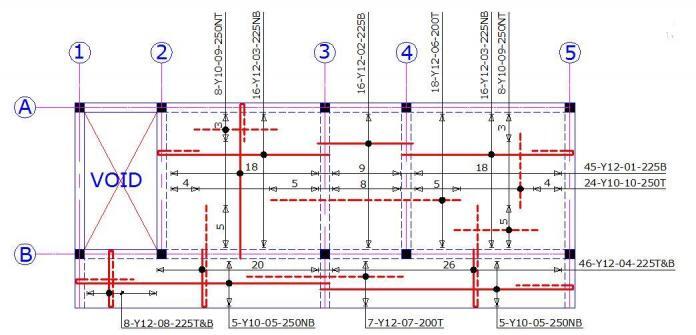
To illustrate how this is done, consider the general arrangement of the first floor of a building as shown below;
Bar Bending Schedule Calculations
Cutting Length of reinforcement = A + B + C – r – 2d (Table 2.19, Reynolds, Steedman, and Threlfall, 2008)
Where;
r = radius of bend (r = 24 mm for high yield 12 mm bars; and 20 mm for Y10mm bars)
d = diameter of bar
Bar Mark 01:
A = 4000 + 230 – 35 = 4195 mm
B = 150 – 2(25) – 10 = 90 mm (including 10 mm tolerance)
C = 230 + 800 – 35 = 995 mm (from detailing considerations 0.2L)
r = 24 (for 12 mm bars)
L = A + B + C – r – 2d = 4195 + 90 + 995 – 24 – 2(12) = 5235 mm
Bar Mark 02:
L = 2230 mm
Bar Mark 03:
A = 3600 + 230 – 35 = 3795 mm
B = 150 – 2(25) – 12 – 10 = 78 mm (including 10 mm tolerance)
C = 230 + 720 – 35 = 915 mm (from detailing considerations 0.2L)
r = 24 (for 12 mm bars)
L = A + B + C – r – 2d = 3795 + 78 + 915 – 24 – 2(12) = 4740 mm
Bar Mark 04:
A = 1080 + 1200 + 230 – 25 = 2485 mm
B = 150 – 2(25) – 10 = 90 mm (including 10 mm tolerance)
C = 1200 + 230 – 25 = 1405 mm (from detailing considerations 0.2L)
r = 24 (for 12 mm bars)
L = A + B + C – r – 2d = 2485 + 1405 + 90 – 24 – 2(12) = 3932 mm
Bar Mark 05:
A = 6000 + 230 – 35 = 6195 mm
B = 150 – 2(25) – 12 – 10 = 78 mm (including 10 mm tolerance)
C = 1200 + 230 – 35 = 1395 mm (from detailing considerations 0.2L)
r = 20 (for 10 mm bars)
L = A + B + C – r – 2d = 6195 + 1395 + 78 – 20 – 2(10) = 7628 mm
Bar Mark 06:
L = 4630 mm
Bar Mark 07:
L = 3830 mm
Bar Mark 08:
A = 1200 + 230 – 35 – 25 – (15) = 1355 mm (including 15 mm tolerance)
B = 150 – 2(25) – 10 = 90 mm (including 10 mm tolerance)
r = 24 (for 12 mm bars)
L = 2(A) + 2(B) + C + D – 3r – 6d = 2(1355) + 2(90) + 2(125) – 3(24) – 6(12) = 2996 mm
Bar Mark 09:
L = 2030 mm
Bar Mark 10:
L = 1830 mm
The final table for the bar bending schedule can be prepared as shown below. However, it is important to include all details in the schedule to avoid confusion.
I hope you find this post helpful… Help tell others about Structville, and keep on visiting us.
Our Facebook fan page is at;
www.facebook.com/structville


Dear UBANI, I looked ur rebar details. Which code? European
or American codes and practices?.. Normally bottom bars shown with dashed lines.Some of the bottom bars in general half of them used as bent up.Good luck..
Top reinforcements are represented with dashed lines, while bottom reinforcements are represented with continuous lines.
See BS EN ISO 3766:2003 Table 1 (No. 16) It explains what Ubani Ranks says.
Actually BS EN ISO 3766:2003 Table 1 (No. 16) says Top Reinforcement is represented with continuous lines while the bottom reinforcement is presented with Extra wide dash lines whenever bottom and top reinforcement is presented on the same drawing.
You did well explaining these things. It seems so easy here till one gets to the field and begin to sweat but with this explanation, any one can grab it
This is apt and interesting.
Now it'll be easy to do some preparation before these thieves come and begin to spill trash.
Thank you for these wonderful tips dear
Excellent tutorial,informative and easy to read.
In plan, dwg shows section looking west. In section dwg shown looking East.
British standards shows bottom reinforcement presented with dashed lines whenever bottom and top reinforcement is presented on the same drawing.
• Thank you very much for your kind words, Adrienne. I appreciate all the support and knowledge you have given me as well! You are an amazing friend and blogger and I’m lucky to have met you in the blogging world!.
BIM Consulting
BIM Solutions
BIM Implementation
Point Cloud to BIM conversion
Fabrication Drawings preparation
MEP F modelling
CAN YOU SEND ANY SIMPLE BUILDING FLAT ROOF BAR BENDING LAYOUT AND SCHEDULE
Please sir do you have a videos base on this please
Is not that clear to me
But if a voice is added i will appreciate
Great explanations bro, if I can get a video explanations it will be better.
Many thanks for all you do!
Very informative article, can you please share reinforcement detailing for a Waffle Slab.
Thanks
Nice explanation sir, thanks for sharing such an informative post.
Thanks so much, it’s really helpful.. God bless you
ENGR Sir, I am finding it a bit difficult to reconcile the bar mark 01 as having a centre to centre dimension as 4000mm instead of 3600mm. For I see the reinforcement mark 01 as along the side Lx = 3600mm of the structure and across the side of Ly = 4000mm
Thank you for this Sir
It’s well explained