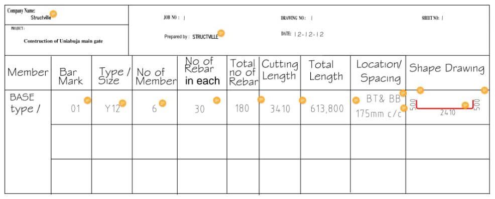
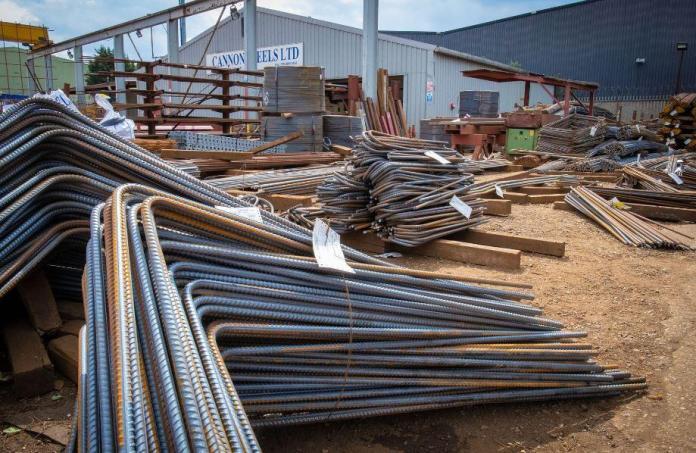
On a construction site, there are different quality control/quality assurance systems to ensure the efficient delivery of a project. One of these is the Bar Bending Schedule (BBS). A bar bending schedule is a document showing the list of structural members, bar mark, type of reinforcement, size of rebar, number of rebars for each member, cutting length, total length, shape, and location/spacing/position of all reinforcements in the working drawing.
Bar bending schedule ensures that reinforcement cutting, bending, and placement are carried out in the most efficient manner on site. It also guides against the excessive waste of reinforcement by minimising the number of useless offcuts. The document is prepared in a manner such that the reinforcement requirements and specification can be recognised and applied without confusion on site. It is issued for different structural elements such as reinforced concrete beams, columns, slabs, foundation, staircase, etc.
In Nigeria, the table showing lists of standard shape codes given in BS8666 doesn’t necessarily conform to the style used in Nigerian construction sites. Some modifications are usually done to avoid confusion, mistakes, and to reduce the workload/effort of the fitters (iron benders). It is very typical for detailers to sketch the actual bending shape on the document instead of referring to the standard shape code.
Read Also…
Preparation of bar bending schedule for slabs
Structural design and detailing standards in Nigeria
The importance of bar bending schedule on a construction site cannot be overemphasized. Some of these includes:
- To serve as a control document for Clerk of work, Inspectors, Detailers, and Structural Engineers on reinforcement
- For quantification of materials by the quantity surveyor during pre-contract and post-contract operations
- To assist steel bender and fixer
- To fast track construction and supervision;
- To plan, detect inconsistencies, and save costs in the handling of reinforcements.
Preparation of Bar Bending Schedule
Preparation of bar bending schedule should not be a haphazard operation. It should begin with the appropriate study of the reinforcement detailing drawings. All inconsistencies or errors (such as repeated bar marks for different types of bars) discovered in the drawing should be reported to the detailer, because as practically as possible, the details of the structural drawing and the bar bending schedule should be synchronised.
The major check lists before the commencement of BBS includes but not limited to the following:
- Check the concrete cover to each face
- Check the lapping length for tensions and compression bars of each structural elements
- Check the direction of bend of each bar
- Group each structural unit and floor by floor. For example, all ground floor elements must be scheduled before proceeding to next floor and all footing must finish before proceeding to starter columns.
- Bar mark must start from 01 and increasing upward consecutively
- Good knowledge of detailing, and considerations affecting the practical construction.
Notations in reinforcement detailing
It is also very important to be familiar with the style used by the draughtsman and its corresponding meaning in the standard detailing practice. For example, in the detailing of a floor slab, the standard method and the corresponding preferred style in Nigeria is as follows:
British Standard
Bottom (face): B1 (outer layer) and B2(second layer)
Top (face): T1 (outer layer) and T2 (second layer)
Nigerian style
B1 = Bottom Bottom (BB) or Bottom (B)
B2 = Bottom Top (BT) or Near Bottom (N)
T1 = Top Top (TT) or Top (T)
T2 =Top Bottom (TB) or Near Top (NT)
It is however common for the notation used in the structural detailing to be given in the design notes.
For example, a main bar of a slab is typically detailed as 12H12-01-250B1 according to standard. However, the common notation used in Nigeria is 12Y12-01-250 BB, which means 12 numbers of high yield deformed bars of 12mm nominal size, at a spacing of 250mm center to center, in the bottom-bottom layer. The bar mark is -01- (Note: BB is the same thing as bottom outer layer). There might not be so much difference in notation based on what is seen above, but it is very important for the detailer to familiarise himself with the loacal standards.
Sections of a Bar Bending Schedule
A typical BBS contains the heading and the schedule section. The heading usually contains information which includes the following:
COMPANY NAME: Provide the name of the company issuing the schedule e.g. Structville Integrated Services Ltd.
PROJECT: Provide the title of the project. E.g. Construction of UniAbuja Main Gate
JOB NO: This is the number assigned to the job by the company or the client.
PREPARED BY: This shows the person that prepared the schedule
DRAWING NO: This gives the particular page in the drawing which references the schedule
DATE: This shows the date the schedule was prepared with reference to any revised schedule
SHEET NO: This shows the page by page documentation/compilation of the schedule
The presentation style of the schedule section of a BBS varies. Different companies always present their schedule in a way that suits them and their workers. Some schedules include the length and number of offcuts expected from a standard length of reinforcement or structural element to guide them in the reuse of reinforcements. For instance, two variants of schedules are shown in the images below.

However, a typical BBS schedule section contains 10 columns in the following order:
[1] MEMBER: This shows the particular member in consideration. E.g base type 1, base type 2, column type 1, column type 2 etc
[2] BAR MARK: This depicts different bar marks present in the drawing. E.g. 01, 02, 03 etc.
[3] TYPE and SIZE: Type relates to whether the specified reinforcement is of high or mild yield, while size depicts the diameter of the bar and typically includes 8, 10, 12, 16, 20, 25, 32, and 40mm bars.
[4] NO. OF MEMBER: This shows the number of times the particular structural elements occur. E.g In the foundation details, how many numbers of Base Type 1 are there?
[5] NO. OF REBAR IN EACH: This means the number of times that particular bar marks occur in that particular member.
[6] TOTAL NO. OF REBAR: This column is the multiplication of columns [5] and [6] to show the cumulative of that particular bar mark.
[7] CUT LENGTH: This column comes next after the previous column. However, in preparing the schedule, the column showing the rebar “shape drawing” has to be done first in order to arrive at the cutting length.
[8] TOTAL LENGTH: This column is the multiplication of columns [6] and [7] to give the overall length of a particular bar mark of a particular element in the entire drawing. The total length is what is used by a Quantity Surveyor to quantify and price. From there, each length or tonnage is gotten as an executive summary. It is also important for data to know how many labourers or man-hours that will be expended on the work.
[9] LOCATION OR POSITION OR SPACING: This is the 9th column on the schedule. Here, if it is a wall, slab or foundation, the layers, and spacing of the bar are shown. If it is a link (stirrup), the spacing is shown and if it is a beam, the position is shown. It is important information for steel fixers.
[10] SHAPE DRAWING: This is the 10th and final column on the schedule. It shows the drawing and the dimensions of all the bends, straights, and the direction each bar is assumed to face after placement. This approach is more detailed and straightforward compared to the main standard where you need a separate sheet of shape code list and separate columns for each dimensions.
For a contractor that uses a fast-track approach, this column is of utmost importance to prefabricate all the shapes and fix all elements ready for placement. E.g all the columns in a story building can be done immediately after mobilization to site. This saves time on the construction program.
Conclusion
The main standard has been domesticated and adapted to be peculiar to the design and construction industry in Nigeria. The Nigerian standard style conforms to BS8666:2005. It is satisfactory and praiseworthy to say that the Nigerian style is comprehensive and easy to understand by a layman. We believe that complex English, Mathematics, Schedule, or Drawing should not be used to confuse sense of good engineering.


Nice one bro
Great job, a really detailed and comprehensive work. Thanks for shearing.
This is really wow. Keeps it up. Thank you
Thank you for your effort. how ca i access the pdf versions of these articals?
Good work done!
Nice article i like it so much
Nice article
Nice one Namesake
Good one. Kudos 👏
usefull work
Our Steel Construction Detailing is providing CAD Services, Consultants Services, Outsourcing Services with an Affordable price. So, If you have lot of work than Connected with US.
Bar Bending Schedule Engineering Services involve the technical analysis and design of reinforcement for construction projects. They can assist in understanding project requirements, suggesting optimal reinforcement layouts, and ensuring compliance with industry standards and codes.
Impressive analysis