Underground water retaining structures have wide applications in residential, commercial, and industrial buildings. According to Lagos State Development Laws (2005), a building with more than 5 floors must have an underground water tank with a minimum capacity of 20,000 litres.
Sometimes, the conventional method of constructing an underground water tank which involves excavating the area, preparing the bottom and slope of excavation, blinding, placing of reinforcements/formwork, bracing, etc before concreting and backfilling may not always be feasible or easy for the contractors. This may be a result of high water table, soft/unstable soils, lack of space, etc. In this case, a top-down construction approach is usually adopted, where the shell of the tank is cast on the ground surface and then sunk to the desired depth in a process similar to the construction of caissons or well foundations.
The advantages of this procedure are;
(1) Improved quality assurance of the tank shells due to easy inspection.
(2) The quality of concreting is assured since it is done on the surface.
(3) The problem of dealing with groundwater is minimised.
(4) The challenge of bracing and supporting the sides of excavation is completely obliterated.
(5) There will be no need for backfilling the sides of the tank
The disadvantages of this procedure are;
(1) The perfect verticality of the tank after sinking may not be guaranteed
(2) The shell will need to cure and achieve enough strength before the sinking will begin, otherwise the sinking stresses might damage the shell
(3) Adequate care will need to be taken during concreting of the base, since it may not be done in a perfectly dry condition.
(4) Extra care is needed to guarantee the water tightness of the base.
(5) Sinking gets difficult when an obstruction is encountered.
Let us now explain the process of constructing and sinking underground water tanks and septic tanks in high water table areas in full.
Step 1: Geometric design
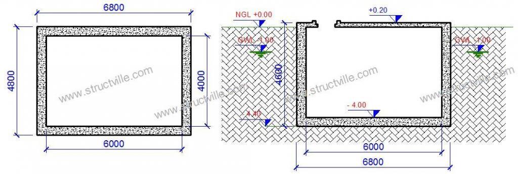
The sizing of the tank should be based on occupancy usage and projected water demand of the building. This can be carried out according to the process described in Ubani (2018). A typical tank dimension (plan and section) is shown in Figure 1.
Step 2: Structural design
The structural design of the tank should take into account the earth pressure, water pressure, imposed load on top of the tank (since the compound will serve as useful space), etc. The sizing of the tank members and the reinforcements provided should satisfy ultimate limit state requirements (for example bending, shear, etc) and serviceability limit state requirements (for example, cracking). The tank should also be able to resist uplift due to groundwater, and the structural engineer should detail the processes required for the water tightness of the structure. These processes are well described in Ubani (2018).
To purchase the full textbook and have it delivered in your mailbox within minutes, click HERE
Step 3: Setting out
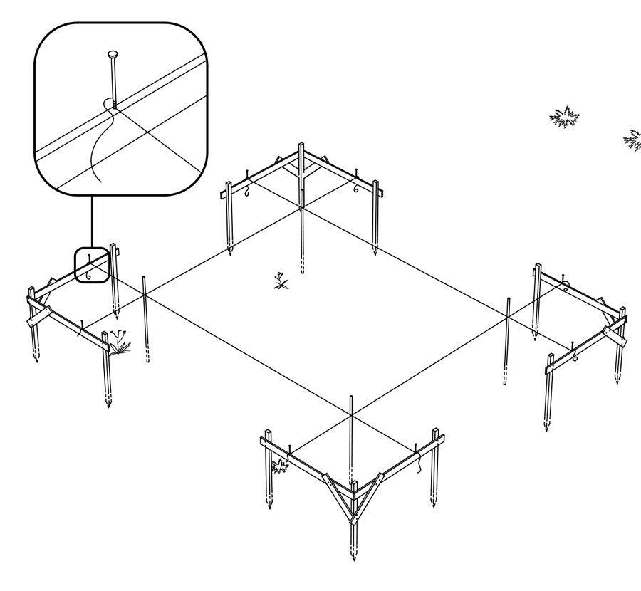
After the design has been properly done and approved, the contractor will need to set out the tank shell so that it will be cast at the exact intended position which is usually specified in the site layout drawing. The tank should be positioned in such a way that the supply and discharge pipes will have minimum obstruction. The contractor can set out the tank using the popular 3-4-5 method and ensure that the edges are square depending on the orientation of the tank. For cylindrical tanks, the appropriate setting out method should be used. Just like in a building, the four edges of the tank (centre to centre) should be established, and a little setback (say 600 mm) established to give the iron benders a good space to position their rebars (see Figure 2). A profile board should be established around the setback, and the exact width of the tank walls established on the profile board.
Step 4: Leveling and blinding
The ground surface (perimeter of the tank walls) should be levelled and made firm so that the base of the walls will be horizontal and level. After that, a mortar blinding should be done on the prepared surface to receive the reinforcements. The width of the blinding should be such that the carpenter will be able to nail or mark his kicker (or whichever method that is adopted) on the blinding. The blinding should be easily broken off as soon as sinking starts.
Step 5: Setting out of kickers
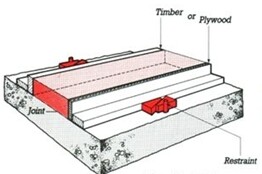
From the established profile lines, the width of the tank walls should be transferred to the blinding on the ground (see Figure 3). The contractor can use laser, spirit levels, iron squares, or whatever instrument at his disposal to achieve this. Perfectly cut pieces of wood can be used as markers for the iron bender to position his rebars properly.
Step 6: Installation of reinforcements
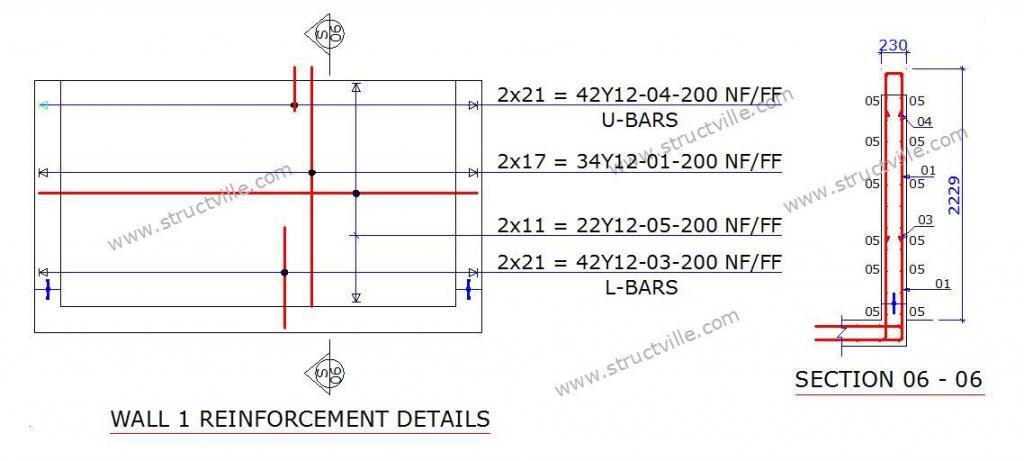
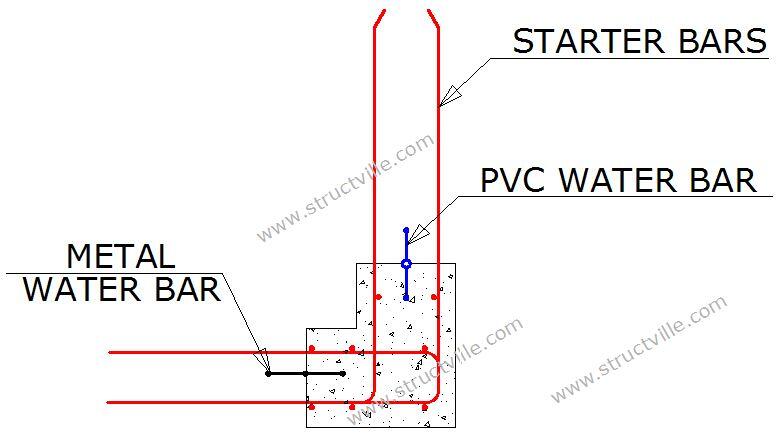
The iron bender should install the reinforcements according to the structural drawing (see example on Figure 4). The concrete cover to the surface facing the soil should typically be taken as 50 mm while the concrete cover to the water storage surface should be taken as 40 mm. The iron bender should ensure that the binding wires are neatly trimmed or pointed inwards after tying because roughly done binding wire can be a source of leakage in the tank. The reinforcement of the wall should be made to project into the base (in L-shape) before the formwork and concreting is done. The water bar (preferably stainless steel water bar) should be installed too as shown in Figure 5.
Step 7: Formwork
The formwork should be properly done and braced as suitable for water retaining structures. Lost ties with hydrophilic water bars wrapped round them with suitable plugs can be adopted to hold the panels in place. The panels should be made with suitable materials such as reusable plastics or marine plywoods. Acrow props should be used to support the bracings to ensure perfect verticality. A small toe of about 150 mm should be provided inwards the tank (see Figure 5). The carpenter or other contractors should also prepare a good scaffold/platform for casting of the concrete.
Step 8: Concreting
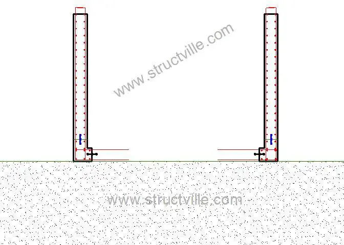
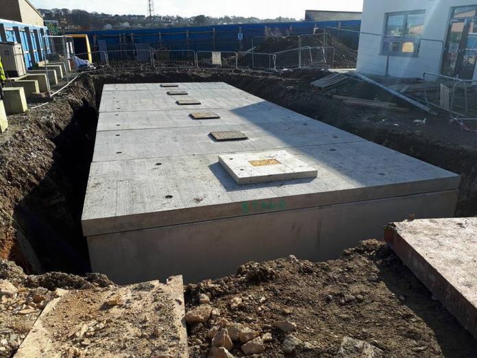
A minimum of grade 30 concrete with water to cement ratio not exceeding 0.5 should be used. Read the specifications for concrete for water retaining structures here. Approved water proofing admixtures should be used also. The concreting should get to the level where the top slab should start. The reinforcement of the walls should be allowed to project into the top slab for proper shear connection. The toe and kickers could be cast first with water bars installed. This will aid the carpenters in achieving a perfect dimension. The first phase of casting is shown in Figure 5 while the full shell is shown in Figure 6. Contractors can adopt a different approach if they wish.
Step 9: Curing and striking
The concrete should be cured and the formwork removed after an approved period of time by the structural engineer.
Step 10: Sinking
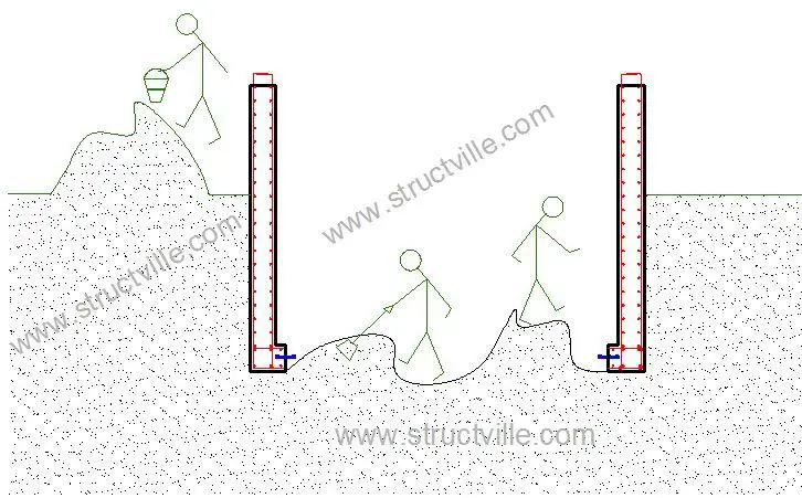
Labourers should climb into the tank and excavate the soil in order to sink the tank to the desired depth. This should be done as carefully as possible and two functional pumping machines (depending on the size of the tank) should be made available to enable the labourers excavate in the dry. The reinforcements projecting into the base should be bent upwards to enable the labourers do their excavation. The sinking is assisted by the weight of the tank which must overcome the frictional resistance from the soil.
Step 11: Concreting the base
After sinking to the desired depth, the base surface should be prepared, cleaned, and properly blinded with concrete of high quality. The reinforcement should be straightened back, lapped properly, and the transverse reinforcements installed. All the water bars should be checked to ensure that they are perfect condition and the remaining portion of the base should be cast to the required thickness with waterproofing admixture. All through this process, there should be constant pumping out of the groundwater. The total weight of the tank at this point should be greater than the upthrust to avoid flotation.
Step 12: Check for water tightness
Typically after casting, you should check the following day to ensure that the tank is dry (note that pumping of groundwater to stay below the base should continue while the concrete gains strength). If the tank is observed to be dry after setting of concrete and pumping of groundwater stops, it means that water exclusion was achieved. The tank can then be flooded with water to check drop in level and to also encourage the autogenous healing of any possible cracks.
References:
(1) Lagos State Physical Planning and Development Regulations (2005): Lagos State Urban and Regional Planning Law. L.S.L.N. No 7
(2) Ubani O.U. (2018): Structural Design of Swimming Pools and Underground Water Tanks. Structville Integrated Services Limited, Lagos Nigeria. ISBN 9789-7869-5413








I love your posts. I learn alot from them. Kudos to you! Keep up the good work. I will like to refer you to step 6. This sentence “The reinforcement of the base should be made to project into the base (in L-shape) before the formwork and concreting is done” “I think it should be the reinforcement of the wall”. Please kindly include your references too. We would like to learn from them.
Thank you very much. I sincerely appreciate. The corrections have been effected.
Nice work bro! Keep up the good work. I learn alot from your posts. I will like to refer you to step 6. “The reinforcement of the base should be made to project into the base (in L-shape) before the formwork and concreting is done”
I think it should be ” the reinforcement in the wall”…..
Also, please kindly include your references so that we can learn from them.
Kind regards.
Beneficial article, just that the casting of the toe with the tank walls will make the sinking more tedious since the toe will no add to the area of contact with the soil.
Also, the metal water bar between the toe and the proposed base may break during the course of sinking either from an unintended impact from shovel or upward push from the soil.
Finally, I must say it that you are really trying puting these articles together. More grease to your elbows.
Thank you Yusuf… I sincerely appreciate your contributions. I acknowledge that casting the toe will make the sinking more tedious. However, I am worried about casting a straight wall because casting the base properly might prove to be another challenging task.
How can you get the required slop at NGL? Remember your discharge pipes from inspection Chambers are sloping down as they go to the septic tank.
Nice article. I learn alot from these. I actually followed all the steps written here but just one thing is not added. About the covering of the manhole, where the water is been pumped out after casting! How do I go about the covering of the hole cause the pressure of water is beyond controlling.