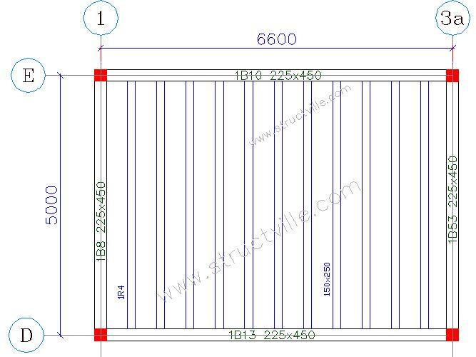
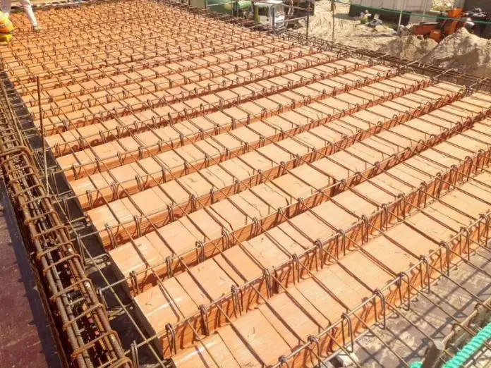
A ribbed slab is a type of reinforced concrete slab in which some of the volume of concrete in the tension zone is removed and replaced with hollow blocks or left as voids. This reduction in the volume of concrete in the tension zone (below the neutral axis) is based on the assumption that the tensile strength of concrete is zero, hence all the tensile stress is borne by the reinforcements in the tension zone. The resulting construction is considerably lighter than a solid cross-section.
This design and construction concept is useful in long-span construction of floors (say spans greater than 5m), where the self-weight becomes excessive when compared to the applied dead and imposed loads, thereby resulting in an uneconomic method of construction. One method of overcoming this problem is to use ribbed slabs which are suitable for longer spans supporting light loading, as in residential or commercial buildings.
Design Example
The layout of a floor slab is shown in Figure 1 below. Design the floor to satisfy ultimate and serviceability limit state requirements. (Concrete grade = 30 MPa, Yield strength of reinforcement = 500 MPa, variable action on floor = 2.5 kPa, Fire rating = 1 hour 30 minutes).


Load Analysis
For 550 mm c/c rib spacing;
Permanent Actions
Weight of topping: 0.050 × 25 × 0.55 = 0.6875 kN/m
Weight of ribs: 0.15 × 0.2 × 25 = 0.75 kN/m
Weight of finishes: 1.2 × 0.55 = 0.66 kN/m
Partition allowance: 1.5 × 0.55 = 0.825 kN/m
Self weight of clay hollow pot = 0.65 kN/m
Total dead load gk = 3.572 kN/m
Variables Action(s)
Variable action qk = 2.5 kN/m2
Variable action on rib beam = 2.5 × 0.55 = 1.375 kN/m
At ultimate limit state; 1.35gk + 1.5qk = 1.35(3.572) + 1.5(1.375) = 6.8847 kN/m
Structural Analysis
Maximum span moment = MEd = ql2/8 = (6.9 × 52)/ 8 = 21.56 kNm
Shear force at the support, VEd = ql/2 = (6.9 x 5)/2 = 17.25 kN
The span should be designed as a T-beam. Follow this link to learn how calculate the effective flange width of beams according to Eurocode 2. In this case the flange width is taken as the centre to centre spacing of the ribs.
Designing the span as a T-beam;
MEd = 21.56 kN.m
Effective depth (d) = h – Cnom – ϕ/2 – ϕlinks
Assuming ϕ12 mm bars will be employed for the main bars, and ϕ8 mm bars for the stirrups (links)
d = 250 – 25 – (12/2) -8 = 211 mm
k = MEd/(fckbd2) = (21.56 × 10⁶)/(30 × 550 × 2112) = 0.0293
Since k < 0.167, no compression reinforcement required
z = d[0.5+ √(0.25 – 0.882k)]
k = 0.0709
z = d{0.5+ √[0.25 – (0.882 × 0.0293)]} = 0.95d = 200.45 mm
Depth to neutral axis x = 2.5(d – z) = 2.5(211 – 200.45) = 26.375 mm < 1.25hf (62.5 mm)
Therefore, we can design the rib as a rectangular section;
Area of tension reinforcement As1 = MEd/(0.87fyk z)
As1 = MEd / (0.87fyk z) = (21.56 × 10⁶) / (0.87 × 500 × 0.95 × 211) = 247.26 mm2
Provide 3H12 Bot (ASprov = 339 mm2)
Check for deflection
ρ = As,req/bd = 247.25 / (550 × 211) = 0.00213
ρ0 = reference reinforcement ratio = 10-3√(fck) = 10-3√(30) = 0.00547
Since ρ ≤ ρ0;
L/d = k [11 + 1.5√(fck) ρ0/ρ + 3.2√(fck) (ρ0 / ρ – 1)(3⁄2)]
k = 1.0
L/d = 1.0 [11 + 1.5√(30) × (0.00547/0.00213) + 3.2√(30) × [(0.00547/0.00213 – 1)(3⁄2)]
L/d = 1.0[11 + 21.098 + 34.416] = 66.514
βs = (500 Asprov)/(fyk Asreq) = (500 × 339) / (500 × 247.26) = 1.371
beff/bw = 550/150 = 3.66 > 3
Therefore multiply basic length/effective depth ratio by 0.8
Therefore limiting L/d = 1.37 × 0.8 × 66.514 = 72.899
Actual L/d = 5000/211 = 23.696
Since Actual L/d (23.696) < Limiting L/d (72.899), deflection is satisfactory.
Shear Design
Maximum shear force in the rib VEd = 17.25 kN
VRd,c = [CRd,c.k.(100ρ1 fck)(1/3) + k1.σcp]bw.d ≥ (Vmin + k1.σcp) bw.d
CRd,c = 0.18/γc = 0.18/1.5 = 0.12
k = 1 + √(200/d) = 1 + √(200/211) = 1.973 < 2.0, therefore, k = 1.973
Vmin = 0.035k(3/2) fck0.5
Vmin = 0.035 × (1.973)1.5 × 300.5 = 0.53 N/mm2
ρ1 = As/bd = 339/(150 × 211) = 0.0107 < 0.02; Therefore take 0.0107
VRd,c = [0.12 × 1.973 (100 × 0.0107 × 30 )(1/3)] × 150 × 211 = 23814.989 N = 23.815 kN
Since VRd,c (23.815 kN) > VEd (17.25 kN), no shear reinforcement is required.
According to clause 6.2.1(4), minimum shear reinforcements may be omitted in ribbed slabs where transverse distribution of loads is possible. But for this design, we will therefore provide minimum shear reinforcement.
Minimum shear reinforcement;
Asw / S = ρw,min × bw × sinα (α = 90° for vertical links)
ρw,min = (0.08 × √(fck)) / fyk = (0.08 × √30)/500 = 0.000876
Asw/Smin = 0.000876 × 150 × 1 = 0.131
Maximum spacing of shear links = 0.75d = 0.75 × 211 = 158.75 mm
Provide H8mm @ 150 mm c/c as shear links.
Slab Topping
A142 BRC Mesh can be provided or H8 @ 250mm c/c
For more information on design and consultancy to accomplish the most challenging design brief, contact the author on info@structville.com. Thank you, and God bless you.


which one is stable , economic and easy construction solid slab or ribbed slab structure ?
Both systems are stable, but the economy depends on the circumstances. Solid slabs are more economical for short spans, while ribbed slabs are more economical for long spans.
How can you design the slab topping to know how to provide the mesh.
You can design the slab topping as a solid slab considering portion of the slabs between two ribs as though it is simply supported.
The reinforcement output will just be like what you have from Engr Ubani.
Please have a second look at the Shear Design. From the values obtained, VRd,c is greater than VEd. i.e., 23.815kN > 17.25kN.
Thank you for that observing that oversight in the use of mathematical symbols. We have corrected it accordingly.
Pls can you throw more light on how rebar mesh should like and points of extreme reinforcement.
can 1 sold slabs weight equal to 2 slabs of Ripped slab?
would you be so kind to answer my question, ❓
thank you for taking your time to explain this.
Kindly provide a detail drawing of your calculations.
Thank you for this. Kindly provide a schematic drawing alongside