During the waterproofing of basements, the architect or structural engineer, or another party such as the contractor or specialised subcontractor, could perform a number of duties related to achieving basement watertightness. Generally, waterproofing systems should be designed to resist the passage of water and moisture to internal surfaces.
As a result, it will be necessary to explicitly identify the roles of each member of the design team in respect to these challenges from the start, as well as to notify the client. The requirement for a resident engineer on large projects should be explored with the client.
The first step in planning a basement waterproofing programme is to ensure that the membrane or other waterproof barrier is raised to the appropriate height. Borehole data isn’t usually a good indicator of the actual level of ground water surrounding a finished basement’s walls. The basement, for example, could be built on a sloping slope to act as a barrier to ground water seepage over the property.
On the uphill side of the structure, this will result in a rise in groundwater level. Borings on a clay site may reveal only sporadic water seepages at depth. Water may gather in the backfilled space surrounding the walls once the basement is finished, especially if the backfilling was placed in a loose state. The compartment could operate as a sump for surface water that collects around the walls and rises to near ground level.
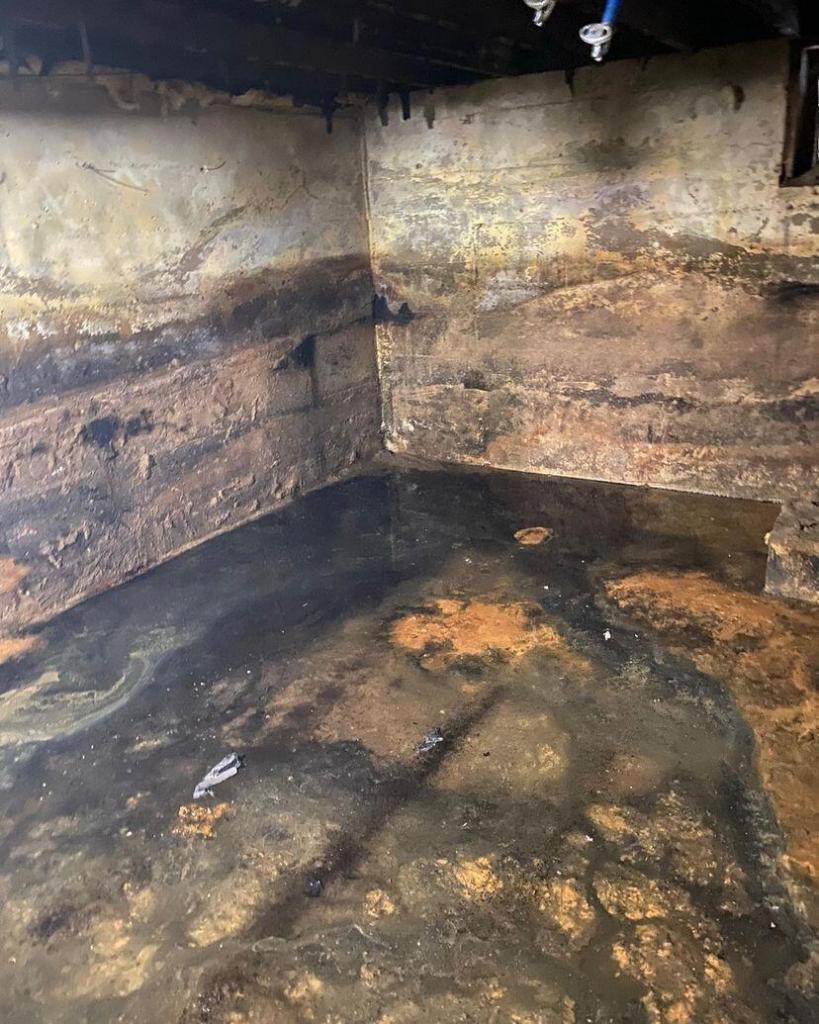
Generally, waterproofing of basements should reach 150mm above the external ground level and link with damp-proofing in the superstructure. This is usually accomplished by connecting a continuous cavity tray to the below-ground waterproofing system. The link between the below-ground and above-ground waterproofing systems should be connected and constructed with the right materials.
When waterproofing is connected to an above-ground structure via a cavity tray, the materials must be able to:
- compress to form a watertight seal, and
- bear the load.
Generally, construction works that are at risk of coming into contact with groundwater and generally require waterproofing include:
- basements
- semi-basements
- below ground parking areas
- underground water tanks and swimming pools
- lift pits
- cellars
- storage or plant rooms
- service ducts, or similar, that are connected to the below ground structure
- stepped floor slabs where the retained ground is greater than 150mm.
Elements forming a waterproofing structure below ground including: foundations, walls and floors, shall adequately resist movement and be suitable for their intended purpose. Issues to be taken into account include:
a) site conditions
b) structural design
c) durability
d) movement
e) design co-ordination.
Grades of Basements
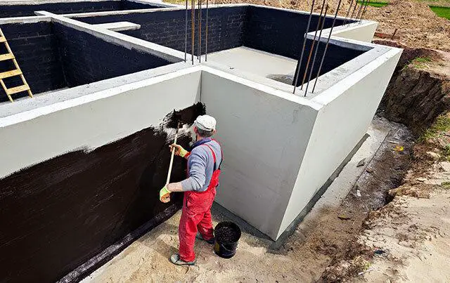
During the design and waterproofing of basements, the client must describe the intended use of the basement space, as well as whether flexibility is required to allow for future changes of usage. The client’s final brief to the design team is usually developed through an interactive consultation process between the client and the design team. The term ‘waterproof’ basement should be avoided at all costs. Rather, acceptable levels of water and vapour penetration should be decided upon – see Table 1.
| Grade of basement | Usage | Performance level | Relative humidity | Dampness | Wetness |
| 1. (Basic utility) | Car parking Plant rooms (excluding electrical equipment) Workshops | Some leakage and damp areas tolerable. Local drainage may be required | 65% normal UK external range | Visible damp patches may be acceptable | Minor seepage may be acceptable |
| 2. (Better utility) | Workshops and plant rooms requiring drier environment than Grade 1 Retail storage | No water penetration but damp areas tolerable dependent on the intended use. Ventilation may be required to control condensation | 35–50% | No visible damp patches, construction fabric to contain less than air dry moisture content | None acceptable |
| 3. (Habitable) | Ventilated residential and commercial areas including offices restaurants etc. Leisure centres | Dry environment. No water penetration. Additional ventilation, dehumidification or air conditioning appropriate to intended use | 40–60% 55–60% for restaurants in summer | None acceptable. Active measures to control internal humidity may be necessary | None acceptable |
| 4. (Special) | Archives Landmark buildings and stores requiring controlled environment | Totally dry environment. Requires ventilation, dehumidification or air conditioning appropriate to intended use | 50% for art storage 40% for microfilms and tapes 35% for books | Active measures to control internal humidity probably essential | None acceptable |
The level of active and passive measures necessary to control the interior environment will be determined by this. BS 8102 includes a useful classification table as well as usage grades. The various grades are intended to qualitatively distinguish the various levels of performance. Table 1 reproduces this information along with recommendations from CIRIA Report R140 (Water-resisting basements), which details how to define the internal climate (temperature, humidity, and wetness) for various purposes within each basement grade.
Relative Humidity (RH) is determined by exterior and internal factors and managed internally by natural or mechanical ventilation within a basement. Waterproofing methods usually have no effect on it. The design team and client should discuss and agree on a plan for controlling RH. The recommended temperature levels are attained by the use of heating and insulation. They, like RH, are unaffected by waterproofing measures and hence are no longer a BS 8102 requirement. Special settings, such as archive or retail storage, require a heating/ventilation system as well as the right style of architecture. In the case of archival storage, BS 5454 provides useful recommendations.
Types of Water-resisting Construction/Protection
After determining the desired basement grade, the next step in the waterproofing of basements is to identify the right type of construction. Types A, B, and C of water-resistant construction/protection are identified in BS 8102. These are barrier, structurally integral, and drained protection, as discussed below.
The location of the water table is regarded crucial in terms of the eventual construction’s possible dangers. With any water table levels and basement grades, Type A, B, or C could potentially be suitable. It should be emphasised, however, that in areas with changeable or high water tables, additional procedures for Type A and piled wall construction are required. It should also be highlighted that reduced permeability of the external earth (where undisturbed) and primary structural wall lowers the risk.
Type A – Waterproofing Barrier Protection
This type of construction, as shown in Figure 3, is entirely reliant on a continuous barrier of a waterproofing membrane, which can be applied to the exterior faces of walls and floors, sandwiched within the structure, or applied to the inner faces of walls. In Type A waterproofing, the structure itself does not prevent water ingress. Protection is dependent on the total water barrier system or water and vapour barrier system applied internally or externally or sandwiched between structural elements in accordance with manufacturers’ instructions. Edge thickenings are to be discouraged with external waterproofing.
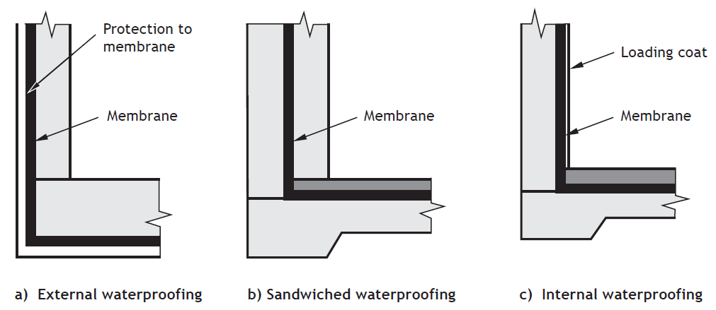
Membranes are usually not applied to floor surfaces and left uncovered because they lack the necessary wear characteristics. If applied to the tops of slabs, a protective slab (or something similar) will be required to keep the membrane in place. A variety of waterproofing materials are available (see below).
Any chosen system should be able to withstand hydrostatic pressure and/or loading effects, as appropriate. Some waterproofing systems may also provide excellent vapour resistance. However, plain polyethylene sheet should not be used as a waterproofing system. The structure is not specifically designed to be watertight in this type of construction, but it may be designed to meet the requirements of BS EN 1992-1-1.
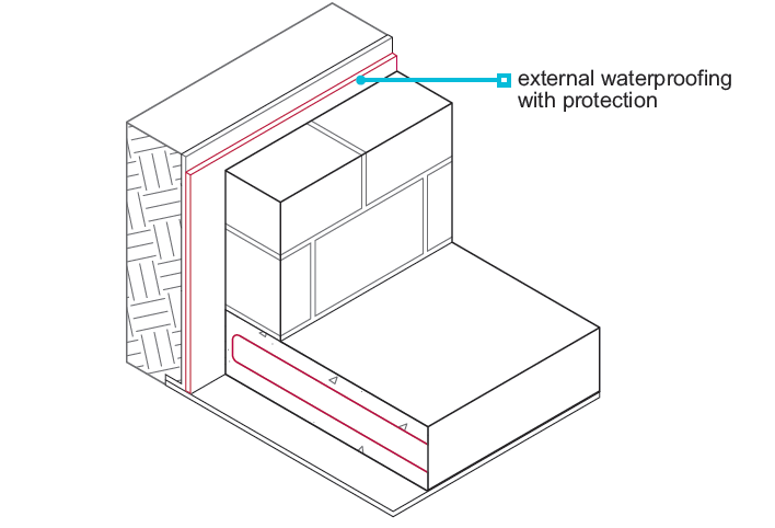
External membranes (or ‘tanking’) will obviously only be suitable where the external face can be accessed for initial construction. Access will limit the scope of subsequent repairs, and locating the source of any defect in a system that is not continuously bonded will be difficult, especially since defects may not become apparent until after construction.
Internally applied membranes will be easier to maintain, but their performance may be harmed by hydrostatic pressures and post-construction attachments. External membranes prevent early-age cracks from autogenously healing and encourage drying shrinkage cracks in concrete. Membranes may be used to protect the concrete structure in extremely aggressive ground conditions.
Type B – Structurally Integral Protection
Type B structure is often a reinforced concrete box that does not rely on applied membranes for water tightness (see Figure 5). The box is designed in accordance with BS EN 1992-3 so that water infiltration is minimised. Crack width limits are determined by the water table and/or the planned grade of use. Design to BS EN 1992-1-1 should be acceptable where the water table and risk are classed as low.
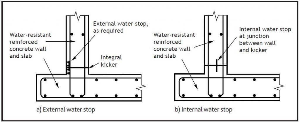
Type B systems acceptable to NHBC include:
- in-situ concrete with or without admixtures and crack widths limited by design
- in-situ high-strength concrete with crack widths limited by design and post-construction crack injections
- precast concrete systems assessed in accordance with Technical Requirement R3.
The structure is unlikely to be totally vapour resistant without membranes, and other measures may be required. As a result, a type B basement may require conversion to a type A or C structure. Alternatively, and more commonly, the consequences of vapour penetration can be easily mitigated by the use of heating and/or ventilation. With the inclusion of vapour barriers, Type B building can accomplish all levels of internal environment.
Design details for reinforced concrete structures should include:
- Concrete specification.
- The type of concrete.
- Concrete strength.
- Proportion of any admixture.
- Proposals for limiting crack widths.
- Consideration of temporary support to the formwork.
- Type and position of reinforcement.
- The method of making good holes in the concrete formed for shutter bolts and tie bars.
- Positioning of structural elements.
- Appropriate tolerances
See also;
Concrete specification for water retaining structures
To avoid faults that allow water to pass through, good workmanship is required. Permeable concrete is a common fault caused by poor craftsmanship, such as inadequate compaction, honeycombed concrete, improper water bar installation, and poor joint preparation and contamination. Under high water table conditions, any water penetration through minor faults can be rectified from the inside.
Type C – Drained Protection
Type C building contains a drained cavity within the basement, which collects any seepage water and drains it to sumps for pumping out (see Figure 6). If any flaws are repaired and the system is maintained, a dry internal environment can be produced with certainty using a drained cavity wall and floor construction.
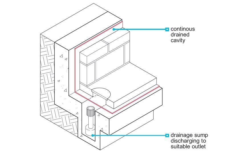
The cavity and pumps may not be able to cope with the flows if the external wall and base slab do not substantially limit water infiltration. Large flows may also cause particles to be lost in the soils around them. Even tiny amounts of drained water may become a problem that necessitates negotiations with authorities.
It should be noted that significant amounts of groundwater pumped into sewers or rivers will normally not be approved by water authorities or the Environment Agency (EA), and specific provisions may be required to avoid loss of fine materials. If a drainage solution is chosen, maintenance requirements must be taken into account in case the drain or filter becomes clogged or fails. If no room is made for maintenance, ineffective drains and filters are likely to cause difficulties.
The cavity should not be used to conceal major leaks, according to CIRIA Report R140. When using water bars, make sure they are continuous and cover all construction joints.
Flooding caused by the failure of drains or pumps, or drain blockage caused by silt or other sediments, are examples of defects that can occur with this type of construction. To collect water infiltration, proprietary channels are often incorporated at the base of the walls. In the case of a blockage, access should be accessible for cleaning the silt and rodding the drains. Some linings prevent access to the cavity behind them, thus it’s obvious that building any interior walls or linings as late as feasible will allow any problems to be seen and rectified.
Rule of Thumb for Structural Design of Water Resistant Basements
Minimum thickness
Preferred minimum thickness of walls and slabs: 300mm
Where thicker consider surface zones of 200mm each face for reinforcement to control shrinkage/thermal cracking
Reinforcement
Typically for water resistant walls:
T16 @ 200 c/c in both faces and in both directions, or
T12 @ 150 c/c in both faces and in both directions
Standard concrete cover
Assumed concrete grade 35 (this should be a minimum)
Put the horizontal reinforcement furthest from earth face.
| Face | Concrete Cover (mm) |
| Earth face of walls where shuttered | 50 |
| Earth face of walls (cast against earth) | 75 |
| External exposed faces of walls | 40 |
| Bottom and sides to base | 75 |
| Internal faces | Greater of 25 or bar diameter |
Waterstops / waterbars
- Required by BS 8102 for grade 1 basements with concrete design to BS 8110
- Give extra “comfort” at construction joints, otherwise total reliance on workmanship
- Not essential but often desirable
- Use external waterstop for basements (preferred)
- Can use centrestop in vertical construction if necessary (e.g. swimming pool), must be carefully supported/kept in place.
Materials for Waterproofing of Basements
Materials for waterproofing of basements should be suitable for the desired site, weather conditions, and any expected movements. There are a lot of proprietary systems out there. Choosing systems with Agreement certifications is a good idea, but the designer should think about the implications of any constraints listed in the certificates. When a vapour-proof system is necessary, further caution should be exercised. In general, it is not a good idea to mix systems.
Structural waterproofing can be done with a variety of products. They have been divided into seven distinct categories based on product kind, form, and application for simplicity of understanding. They are considered barrier systems for Type A protection, with the exception of Category 2. (but may be combined with Type B protection). Category 2 is a Type C protective mechanism that generates a drainable cavity. Below is a brief description of each category.
Category 1 – Bonded sheet membranes
These are cold-applied or heat-bonded to the structure. They are flexible and can accommodate minor movements. There are also composite sheet membranes, which can be fixed to vertical formwork or laid on the ground prior to pouring the slabs.
Category 2 – Cavity drain membranes
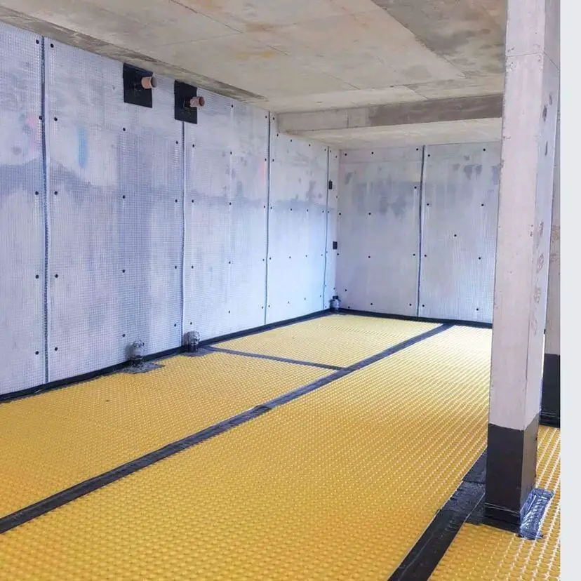
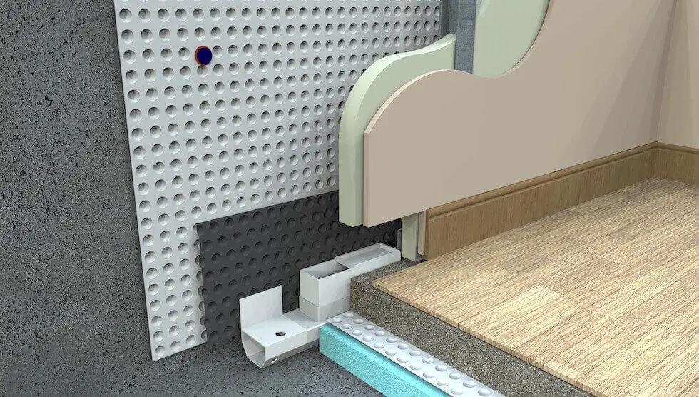
These are high-density polyethylene sheets placed against the structure. The dimples form the permanent cavity. These are generally used internally. They are flexible and are able to adapt to minor settlement and shrinkage of substrate. These are not waterproofing membranes in themselves; but facilitate drainage of any water ingress (see Figure 8).
Category 3 – Bentonite clay active membranes
These are sheets of sodium bentonite clay sandwiched between two layers of geotextile or biodegradable cardboard. When the clay meets water, it can swell to many times its original volume sealing any gaps or voids in the membrane. This category of membrane is used externally. Bentonite systems can be either bonded or unbonded. Where bonded, the system is simple to apply with minimum preparation of the substrate. The efficacy of the system under alternating drying and wetting conditions should be verified with manufacturers. It should not be used in acidic or excessively alkaline soil.
Category 4 – Liquid applied membranes
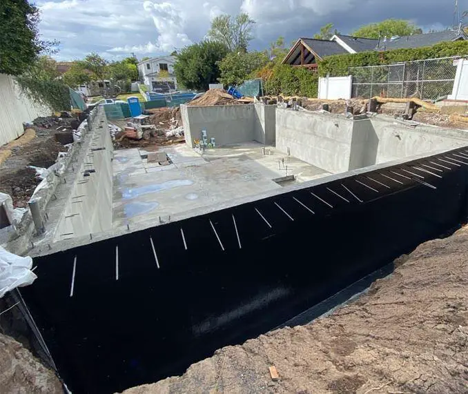
These one- or two-part systems are applied cold as a bitumen solution, elastomeric urethane or modified epoxy. A loading coat (a layer of material designed to hold a Type A waterproofing compound in place when resisting water pressure) will be required if applied internally, and it must be strong enough to adhere to a suitable substrate and sustain hydrostatic pressure. In Type B protection, they can be utilised solely as a vapour barrier if the building can take the load. The membrane’s continuity is preserved due to its lack of joints. It is simple to apply, but proper surface preparation is required. They can protect the structure from aggressive soils and groundwater when applied externally. Minor substrate motions can be accommodated because the substrate is elastic and flexible.
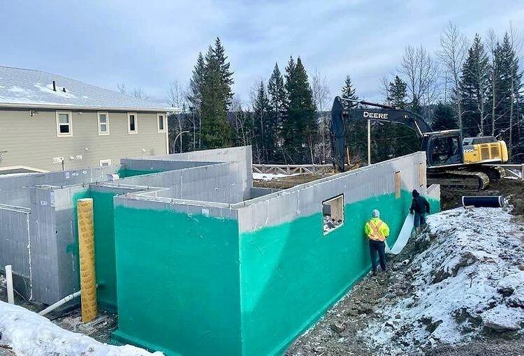
Category 5 – Mastic asphalt membranes
As a hot mastic liquid, these are applied in three coats. They harden into a waterproof layer as they cool. The application can be external or interior, but if applied internally, a loading coat is required. The likelihood of a defect in one coat being carried across all of the membrane’s coats is low. For complex foundation profiles, externally applied membranes are often unsuitable.
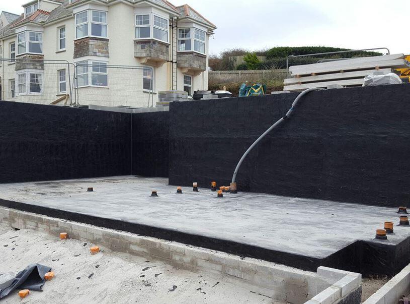
Category 6 – Cementitious crystallisation active systems
These slurry coatings react with free lime in concrete, renders or mortars and block hairline cracks and capillaries. The chemicals remain active and will self-seal leaks. These products will not waterproof defective concrete (e.g. honeycombed areas).
Category 7 – Proprietary cementitious multi-coat renders, toppings and coatings
These coatings usually incorporate a waterproofing component and are applied in layers generally internally but may also be external. They are effective against severe ground water infiltration. Mechanical fixings through the system should be avoided.
Finally, ancillary components should be assessed as part of the waterproofing system. Alternatively, an assessment of compatibility and satisfactory performance should be provided for materials and products that are interchangeable between different systems.
Ancillary components include:
- preformed junctions and corners
- reinforcement
- water stops/water bars
- hydrophilic strips.






Very informative
So, great full
Very informative and helpful
LOOKING GOOD AND HELPFUL INFORMATION TO UPGRADE TECHNICAL AND CIVIL CONSTRUCTION KNOWLEDGE STEP BY STEP. HELPFUL FOR FUTURE GENERATIONS.
It really helped when you said that the materials for the basement waterproofing system should be appropriate for the site, weather conditions, and movements of the area where the property is located. I have to ask various professionals here in Cincinnati, Ohio so that I can get the best idea of what to get for my property. This is for the house I just bought, since it still needs a little work before I move into it which is why it was at a lower price.
I find it interesting when you said that there are different types of products to be used for waterproofing services and there are even seven distinct categories to think about when it comes to those items. In that case, the best thing we can do is to look for a basement waterproofing tract or to advise or recommend the right product and processes for our home. And it might also matter to consider the weather or climate here before choosing any technique or method.
I liked it the most when you shared that basement generally needs waterproofing. My friend wants to opt for basement moisture waterproofing. I should advise him to turn to a company with an A+ rating from the Better Business Bureau.
I’m glad you said that the water tightness of your basement would be inspected and assessed to consider the best process for the waterproofing project. My cousin told me a few days ago that he was looking for a waterproofing solution to prevent molds in their basement walls and floors. He asked if I had thoughts on the best basement waterproofing project approach. I’ll tell him he can consult a basement waterproofing service as they can provide information about the process of waterproofing. I value this enlightening waterproofing guide article for proper planning.
Areas like basements at home could indeed need a lot of waterproofing work if you want to keep them safe. Since moisture issues can cause mold if you’re not aware of them, I feel like this is exactly what we’ll need to remember to do as early as possible so our project can go well. I’ll go and look for a basement damp-proofing expert who can help me out with my project as early as now.
Waterproofing basements is crucial to prevent water and moisture from damaging internal surfaces. The process involves the coordinated efforts of architects, engineers, and contractors. Clear role definitions and client communication are essential from the outset. Key steps include raising the waterproof barrier to the correct height and considering site-specific groundwater levels, especially on sloping sites. Proper planning and execution ensure the basement remains dry, safeguarding the structural integrity and usability of the space.