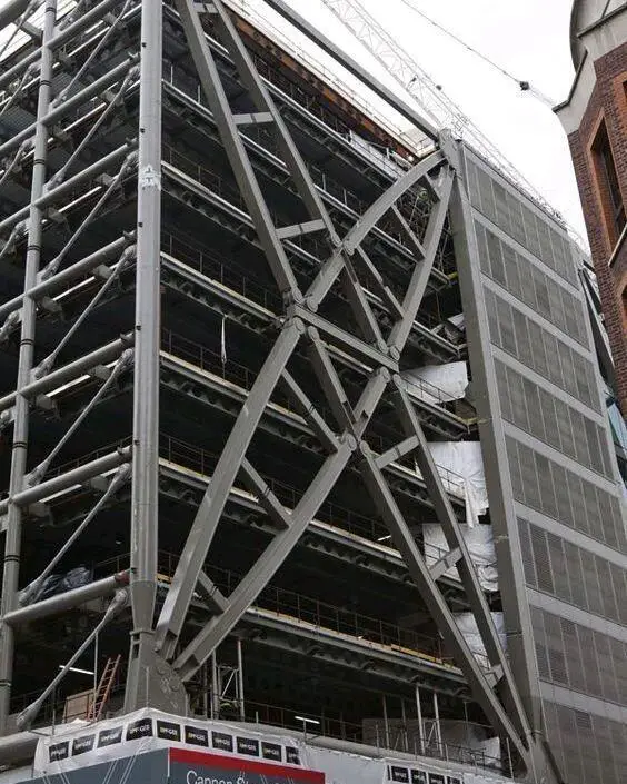
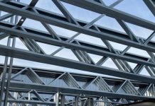
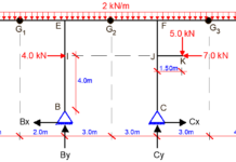
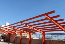
A braced frame is a structural system that is prevented from undergoing excessive sidesway under the effect of lateral loads by the provision of diagonal steel members (for steel structures) or shear walls/cores (for reinforced concrete structures). Therefore, braced frames are effective structural solutions for resisting lateral loads due to wind or earthquake in civil engineering buildings and structures. In effect, they provide the lateral stability needed in structures.
The stabilising members in a braced frame are usually made of structural steel, which can be very effective in resisting tensile and compressive forces. Most of the multi-story braced frames in the UK are designed as ‘simple construction,’ with nominally pinned connections between beams and columns. The horizontal force resistance of buildings in simple construction is provided by the bracing systems or cores in the global analysis.
As a result, the beams are designed to be simply supported, and the columns are merely designed to withstand moments caused by a minimal eccentricity in the beam-to-column connection (in conjunction with the axial forces). As a result, there is no need to consider pattern loading when calculating design forces in the columns.
The Eurocodes take the ‘simple construction’ design approach into account. If the joint is categorised as ‘nominally pinned’ according to BS EN 1993-1-8, and this classification is based on previous satisfactory performance in similar instances, a ‘simple’ joint model, in which the joint is assumed not to transfer bending moments, may be utilised. The beam reactions are applied eccentrically to the columns in the regularly used joint configurations in the UK, which assume a pinned connection but also assume that the beam reactions are applied eccentrically to the columns.
The global analysis model may therefore assume pinned connections between the columns and the beams for braced frames constructed in accordance with BS EN 1993-1-1, provided that the columns are designed for bending moments due to eccentric reactions from the beams.
Bracing Systems
The beams and columns in a multi-story building are typically placed in an orthogonal pattern in both elevation and plan. Two orthogonal bracing systems provide horizontal force resistance in a braced frame building:
- Vertical Bracing, and
- Horizontal bracing
Vertical bracing
Vertical bracing (between lines of columns) provides load pathways that carry horizontal forces to the ground level while also providing stiff resistance to overall sway. The vertical bracing planes in a braced frame multi-story building are commonly provided by diagonal bracing between two lines of columns, as shown in Figure 2.
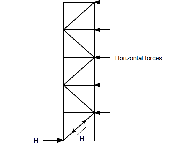
Single diagonals, as shown, must be designed for either tension or compression, however crossing diagonals can be utilised with narrow bracing components that do not resist compressive stresses (then only the tensile diagonals provide the resistance). The floor beams participate as part of the bracing system when crossing diagonals are used, and it is considered that only the tensile diagonals produce resistance (in effect a vertical Pratt truss is created, with diagonals in tension and posts in compression).
Vertical bracings must be designed to withstand the following forces:
- Wind forces
- Equivalent horizontal forces, which illustrate the effects of initial imperfections
- Sway-induced second-order effects (if the frame is flexible).
For the right combinations of actions, forces in specific members of the bracing system must be determined. Design forces at ULS are anticipated to be the most onerous for bracing members due to the combination where wind load is the dominating action. Bracing members that are inclined at about 45 degrees are preferred whenever possible.
This results in an efficient system with low member forces compared to other configurations, as well as compact connection details where the bracing meets the beam/column joints. The sway sensitivity of the structure will be increased by narrow bracing systems with steeply inclined interior elements. Structures with extensive bracing will be more stable.
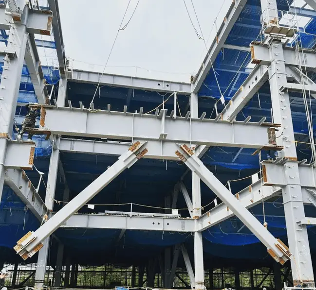
In a building, at least two vertical bracing planes in each orthogonal direction must be provided to avoid disproportionate collapse. There should be no considerable component of the structure braced by only one plane of bracing in the direction being studied since there would be no other restraint system in that direction if the local failure occurred in one of its parts.
Types of Vertical Bracing
Different types of bracing systems can be adopted for the lateral stability of framed structures. Diagonally Braced Frames, V-Braced Frames, and Chevron Braced Frames are three popular forms of concentrically braced frames. Studies have shown that the seismic excitation due to earthquake can be efficiently resisted by concentrically braced frames. This means that the braces, columns, and beams resist lateral seismic acceleration predominantly through axial forces (tension and compression) and deformation.
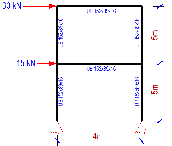
In order to appreciate the effects of bracing, let us consider the unbraced frame loaded as shown in Figure 4;
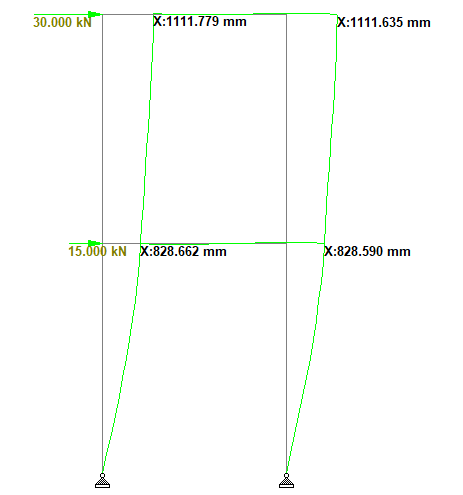
Under the applied load, the deflection in the frame is shown in Figure 5;
Now, let us consider the effects of different bracing systems on the deflection behaviour of the frame.
Single Diagonal Bracing
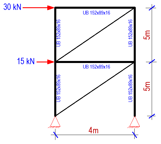
Single diagonal bracing is considered effective in resisting lateral loads. They are formed by introducing single diagonal members to the frame (trussing). When lateral load is applied to the braced frame, the diagonal braces are subjected to compression while the horizontal web acts as the axial tension member in order to maintain the frame structure in equilibrium. If we consider the frame shown in Figure 4, let us introduce diagonals with the same member property UB 152 x89x16 as shown in Figure 6;
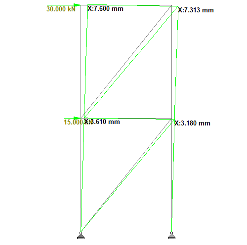
Interestingly, the introduction of single diagonal bracing reduced the lateral displacement of the frame by 99.34% as shown in Figure 7. In this case, the columns on the left-hand side and the diagonals of the braced frame were in tension, while the horizontal beams and the columns on the right-hand side were in axial compression.
Cross Bracing (X-Braced Frames)
In cross-braced frames, two diagonal members cross each other to form an X-shape. These simply need to be tension-resistant, with one brace functioning at a time to resist lateral loading, depending on the loading direction. Steel cables can therefore be utilised for cross-bracing. The performance of the tension braces in the design of single diagonal braces and X-bracing depends on the stiffness, resistance and ductility.
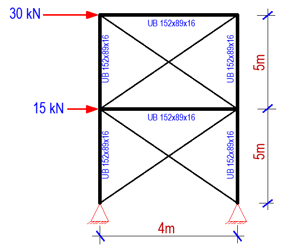
When cross bracing is applied to the frame, the deflection is shown in Figure 9;
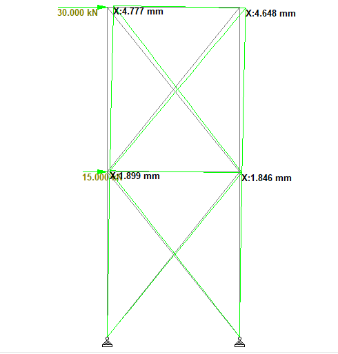
The result shows that x-braced frame is more efficient than single diagonal cross bracing in reducing the lateral displacement of the structure. However, this usually comes at the expense of extra cost, and increased bending of the horizontal beams. From the structural behaviour, it was observed that one of the braces is in tension, while the other is in compression (depending on the direction of the load).
V-Bracing (Chevron Bracing)
A chevron bracing is formed by introducing v-shaped braces into the frame. Chevron braces are known for their high elastic stiffness and strength. Unlike cross-bracing, chevron bracing is also effective in increasing architectural functionality. This is necessary in order to arrange the window and entrances in the braces bay.
However, under the effect of lateral load, however, uneven forces are formed on the braces. This is because the compression bracing will deform while the tension braces will remain in place to maintain the tension force during lateral loading.
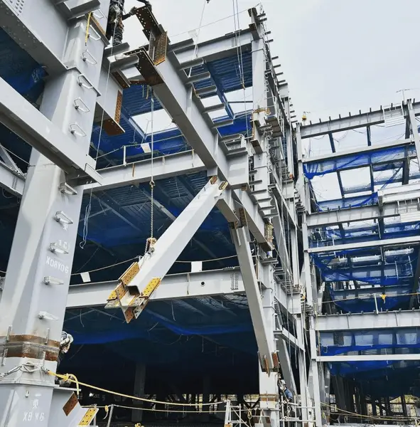
Under earthquake load, the tension and compression braces have a substantial influence on the unbalanced distributed force, which can induce elastic deflection of the braced frame. As a result of the deformation of the braces, the entire braces frame performs poorly. This means that at each level of braces bay, one brace resists the tension while the other brace resists compression. Before the buckling point, they both distribute the lateral stress equally in the elastic range.
The tension braces, on the other hand, maintain their tension after buckling, but the compression braces lose all of their axial load capacity. This contributes to the unbalanced distributed lateral load and result in a significant bending moment at the beam-brace intersection. As a result, the mid-span beam develops a plastic hinge and collapses due to its inability to withstand downward stresses.
For the frame loaded as shown in Figure 4, Chevron braces are were introduced as shown in Figure 11;
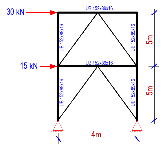
The deflection of the frame under lateral load is shown in Figure 12;
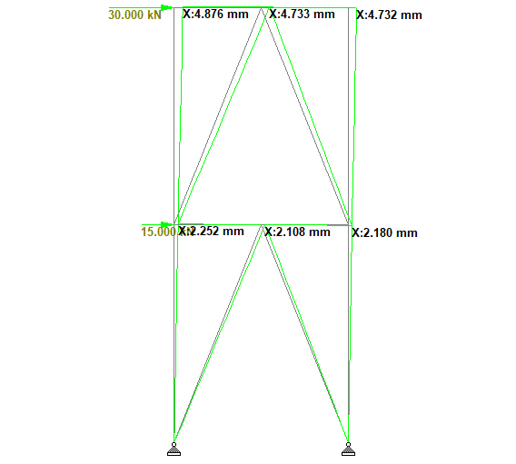
The deflection behaviour of the x-braced frame and the chevron bracing are quite comparable.
Summary of the lateral deflection is shown in the Table below;
| Frame Type | Lateral Displacement (mm) |
| Unbraced frame | 1111.635 mm |
| Single diagonal bracing | 7.313 mm |
| Cross Bracing (X-bracing) | 4.648 mm |
| C-bracing (Chevron Bracing) | 4.732 mm |
Horizontal bracing
At each floor level, horizontal bracing (usually provided by floor plate action) provides a load route for horizontal forces (mostly from perimeter columns owing to wind pressure on the cladding) to be transferred to the vertical bracing planes.
At each floor level, a horizontal bracing system is required to transfer horizontal forces (mostly those transferred from the ends of perimeter columns) to the vertical bracing planes that provide resistance to horizontal forces. In multi-story braced frames, there are two types of horizontal bracing systems:
- Diaphragms
- Discrete triangulated bracing.
In most cases, the floor system will operate as a diaphragm without the need for extra steel bracing. If there is no slab at roof level, bracing, also known as a wind girder, may be necessary to carry the horizontal forces at the top of the columns.
If the horizontal bracing system at each floor level is relatively stiff (as it is when the floor acts as a diaphragm), the forces carried by each plane of vertical bracing are determined by its relative stiffness and placement, as well as the location of the horizontal forces’ centre of pressure.
Horizontal Diaphragm
Permanent formwork, such as metal decking connected to the beams by through-deck stud welding, and in-situ concrete infill, provide an effective rigid diaphragm to transfer horizontal forces to the bracing system. If precast concrete planks are to operate as a diaphragm, due thought must be given to ensure effective force transfer.
Planks and steelwork can have a coefficient of friction as low as 0.1, and even lower if the steel is painted. This will allow the slabs to glide over the steelwork and move relative to one another. Grouting between the slabs will only solve part of the problem; for significant shears, a more positive fastening system between the slabs and from the slabs to the steelwork would be necessary.
Reinforcement in the topping might be used to connect the planks. This could be mesh or ties running along both ends of a row of planks to ensure the entire panel functions as one. In most cases, a 10 mm bar at half the depth of the topping will suffice.
One of two approaches can be used to connect to the steelwork:
- Provide ties between the topping and an in-situ topping to the steelwork (known as a ‘edge strip’).
- Enclose the slabs with a steel frame (on shelf angles, or particularly provided limitation) and fill the gap with concrete. Shear connections should be installed on the steel beam to transfer forces between the in-situ edge strip and the steelwork.
The capacity of the connection should be verified if plan diaphragm forces are transferred to the steelwork by direct bearing (usually the slab bears on the face of a column). The plank’s capacity is often restricted by local crushing. In every scenario, in-situ concrete should be used to fill the gap between the plank and the steel.
Without additional safeguards, timber floors and floors made of precast concreted inverted tee beams and infill blocks (often referred to as “beam and pot” floors) are not considered suitable diaphragms.
Discrete Triangulated Bracing
A horizontal system of triangulated steel bracing is indicated when diaphragm action cannot be relied upon. In each orthogonal direction, a horizontal bracing system may be required. Horizontal bracing systems often span between the ‘supports,’ which are the vertical bracing’s positions. This configuration frequently results in a truss that spans the entire width of the structure and has a depth equal to the bay centres. Warren trusses, Pratt trusses, and crossing members are all common floor bracing arrangements.

