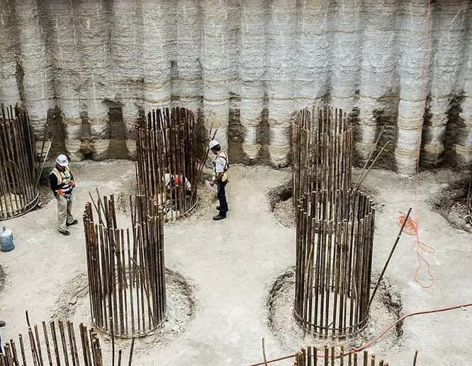
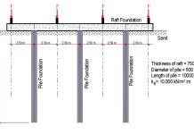
In many cases, the load bearing capacity of a group of vertically loaded piles is smaller than the sum of the capacities of the individual piles that make up the group. The elastic and consolidation settlements of the group are always bigger than a single pile carrying the same working load as each pile within the group. This is due to the fact that the zone of soil or rock that is stressed by the entire group is significantly wider and deeper than the zone beneath a single pile.
Even while loading tests on a single pile have shown good performance, group action in piled foundations has resulted in several recorded examples of failure or excessive settlement. It is therefore very important to check the settlement and bearing capacity of pile groups.
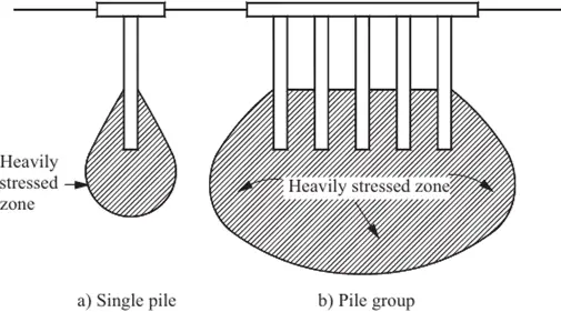
A single pile driven to a satisfactory depth in a compact or stiff soil layer underlain by soft compressible clay is a classic case of foundation failure. When a single pile is loaded (Figure 1(a)), the latter formation is not significantly stressed, but when the weight from the superstructure is applied to the entire group, the stressed zone spreads down into the soft clay. The group may then experience excessive settlement or full shear failure (Figure 1(b)).
The allowable load on pile groups is frequently established by ‘efficiency formulas,’ in which the group’s efficiency is defined as the ratio of the average load per pile when the entire group fails to the load at failure of a single comparable pile. While there are so many of pile group efficiency equations to choose from, these equations should be used with caution, as they may be little more than a fair guess in many circumstances. The Converse-Labarre Formula is one of the most extensively used group-efficiency formulae;
Eg = 1 – {[θ(n – 1)m + (m – 1)n]/90mn} ——- (1)
Where;
m = number of columns in the pile group
n = number of rows in the pile group
θ = tan-1(d/s) in degrees
d = diameter of the piles
s = spacing of the piles
Most of the varying efficiency ratios are solely developed based on personal experience, with no connection to soil mechanical theory. As a result, Tomlinson (2004) argues that this is not a desirable or logical approach to the problem, and instead prefers to design methods based on the assumption that the pile group behaves as a block foundation with a degree of flexibility that is determined by the rigidity of the capping system and the superimposed structure.
When applying soil mechanics methods to the design of pile groups, it’s important to keep in mind that, whereas the installation method influences the selection of design parameters for skin friction and end bearing in the case of a single pile, the installation procedure has less of an impact when considering group behaviour.
This is due to the fact that the zone of soil disturbance occurs only within a few pile diameters surrounding and beneath each individual pile, whereas the soil is considerably stressed to a depth equal to or higher than the group’s breadth (Figure 1(b)). The majority of this zone is located below ground level, which has been disrupted by the pile construction.
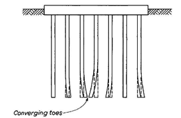
If two or more piles depart from alignment and come into close contact at the toe, there is a risk of severe base settlement when piles are erected in small numbers. As shown in Figure 2, the toe loads are concentrated over a limited region, and while failure would not occur if the end bearing safety factor was appropriate, the settlement would be greater than when the piles were spaced at their design spacing. As a result, the piles in the group would undergo differential settlement.
Spacing of Piles in a Group
In clays, the selection of a centre-to-centre spacing of at least three pile diameters, with a minimum of 1m, is a precaution against severe base settlement due to close alignment of piles. For friction piles, BS 8004 requires a centre-to-centre spacing of not less than the perimeter of the pile or three times the diameter of circular piles.
For piles carrying their load mostly in end bearing, closer spacing can be used, but the distance between neighbouring piles must not be less than their minimum width. The spacing of piles with larger bases requires special attention, including a study of the interaction of stresses and the impact of construction tolerances.
The Swedish piling code gives the following minimum centre-to-centre spacing for end-bearing and friction piles;
| Pile Length (m) | Circular Pile | Square Pile |
| Less than 10 m | 3 x Diameter | 3.4 x width |
| 10m – 25m | 4 x Diameter | 4.5 x width |
| > 25 m | 5 x Diameter | 5.6 x width |
In all cases the centre-to-centre spacing should not be less than 0.8m.
Ultimate Bearing Capacity of Pile Group in Clay
There is no risk of general shear failure of the group if piles in groups are driven through soft clays, loose sand, or fill to end in a stiff clay, as long as there is an enough safety factor against single pile failure. However, the group’s settlement must be determined.
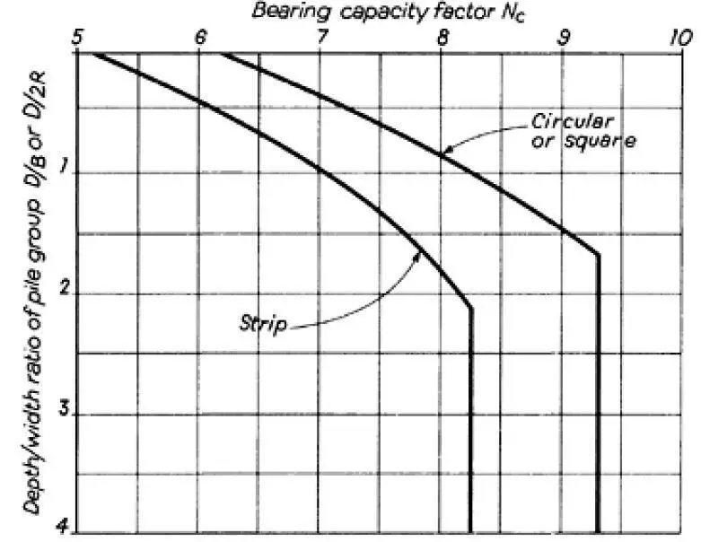
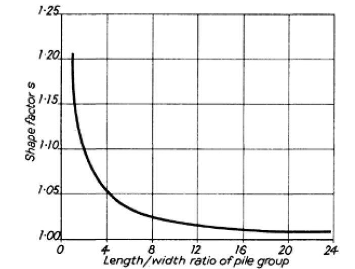
If a group of piles must be terminated totally within a soft clay (which is not recommended), the group’s safety factor against ‘block failure’ must be determined. Equation (2) is used to compute the ultimate bearing capacity of the block of soil enclosed by the group.
Q = 2D(B + L)ca + 1.3cbSNcBL ——- (2)
where;
D is the depth of the piles below ground level,
B is the overall width of the group,
L is the overall length of the group,
ca is the average cohesion of the clay over the pile embedment depth,
cb is the cohesion of the clay at the pile base level or within the zone of soil below the base affected by the loading,
s is a shape factor, and
Nc is the bearing capacity factor.
The remoulded shearing strength should be considered if the pile group is required to handle the full working load within a few days or weeks of the piles being put. Because the majority of the zone in which general shear failure would occur remains undisturbed, undisturbed cohesion can be employed for cb in most circumstances. Nc values are determined by the group’s depth to width ratio (Figure 3). The length to width ratio determines the shape factor s, and suitable values are indicated in Figure 4.
Ultimate Bearing Capacity of Pile Group in Sand
There is no risk of block failure of a pile group terminated in and applying stress to a cohesionless soil if each individual pile has an acceptable safety factor against failure under compressive pressure. The piles must be designed with high-end bearing loads for economy.
When piles deviate from their intended line, as with piles terminating in clay, there is a potential of differential settlement between adjacent piles if the toe loads of a small group become concentrated in a small location. The simplest way to avoid this is to keep the piles separated by a reasonable amount of space.

