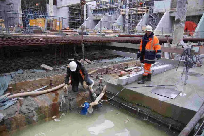
Groundwater is typically regarded as one of the most challenging problems encountered during excavation for civil engineering construction works. To control seepage of water into excavations, expensive and continuous pumping may be required, and the constant flow from the surrounding ground may cause settlement of adjacent structures.
The sides of open excavations are susceptible to eroding or collapsing if they are subjected to heavy inflows. Under certain conditions, the base can become unstable due to seepage towards the pumping sump, or if the bottom of excavation in clay is underlain by a pervious layer containing water under artesian pressure.
However, with knowledge of the soil and ground-water conditions and an understanding of the laws of hydraulic flow, it is possible to adopt ground-water control methods that will ensure a safe and cost-effective construction plan under any circumstances. Before beginning work, it is essential to collect all important data, and this aspect should not be overlooked during the site investigation phase.
Sometimes, after an excavation has been begun, more pumps are brought to the site, and with great difficulty the excavation is taken deeper until the inflow is so heavy that the sides start collapsing, endangering adjacent roads and buildings, or ‘boiling’ of the bottom is so extensive that a suitable base for foundation concreting cannot be obtained.
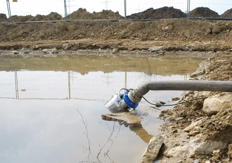
At this point, the contractor may give up and seeks assistance from outside sources to install a wellpointing or bored well system for ground-water lowering, or resorts to underwater construction. The ground-water lowering systems may be effective, but the overall cost of abortive pumping, extra excavation of collapsed material, making good the damage, and standing time of plant and labour would have been significantly higher had the ground-water lowering system been used in the first place.
Due to a lack of understanding of the capabilities of modern groundwater lowering systems, there have been instances in which caissons have been used for foundations in water-bearing soils when conventional construction with the aid of such systems would have been perfectly feasible and significantly less expensive.
Figure 2(a) shows the flow line of groundwater under a relatively low head into an open excavation in permeable soil. The water surface is depressed toward the pumping sump, and as a result of the low head and flat slope, seepage lines do not emerge on the slope and conditions are stable.
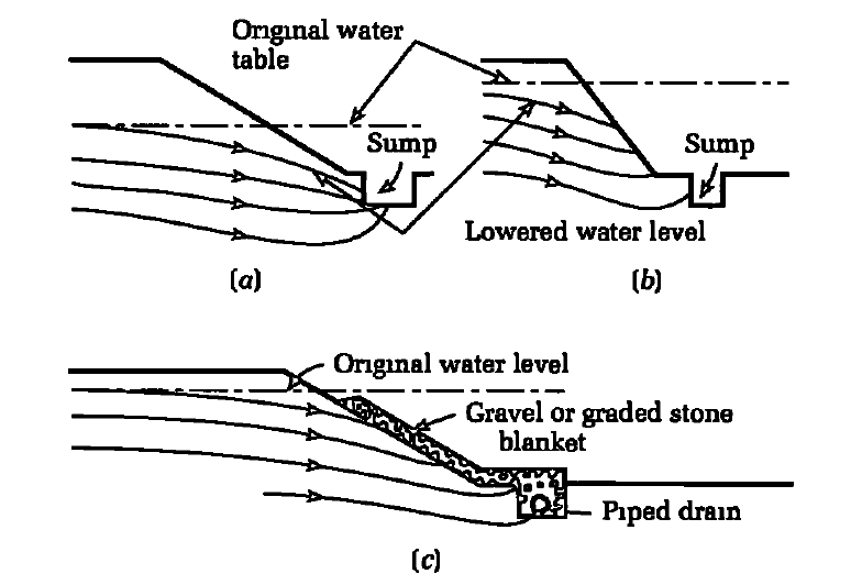
Nevertheless, if the head is increased or the slopes are steepened, the water will flow away from the face, and if the velocity is high enough, it will cause the movement of soil particles and erosion down the face, resulting in undermining as well as the collapse of the upper slopes (Figure 2(b)). The solution is to level the slopes and cover the face with a graded gravelly filter material that allows water to pass but traps soil particles (Figure 2(c)).
Graded filters will need to be properly designed, otherwise erosional instability might occur. This type of erosional instability is most likely to occur in fine or uniformly graded sands. Since well-graded sand gravels act as natural filters and their higher permeability prevents the emergence of flow lines on the excavated face, there is a significantly reduced risk of complications when using these materials.
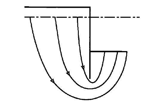
In the case of close-timbered or sheet-piled excavations, the flow lines descend behind the sheet piling before ascending into the excavation (Figure 3). This condition of upward seepage is especially prone to cause instability, known as “piping” or “boiling,” when the velocity of the upward-flowing water is sufficient to suspend soil particles.
The preceding cases are generally applicable to groundwater flow in permeable soils, such as sands and gravels, or similar materials with relatively low proportions of silt and clay. Little or no difficulty is encountered when excavating in clays. When groundwater is present, it typically seeps through fissures and can be removed by pumping from sump wells.
Typically, the flow velocity is so low that there is no risk of erosion. Silts, however, are extremely problematic. They are permeable enough to allow water to pass through, but their permeability is low enough to make any system of ground-water lowering by wellpoints or bored wells a time-consuming and expensive process. Typically, ground water in rocks seeps from the face as springs or seeps through fissures or permeable layers. There is no risk of instability unless heavy flows pass through a brittle, fractured rock.
Generally, water in rock excavations can be pumped from open sump pits, with the exception of when foundation concrete is intended to be placed against the rock face. If the springs or weeps are strong, the water will wash the cement and fines from the unset concrete and flow out through the concrete’s surface.
The standard procedure is to construct the pumping sump at the lowest point of the excavation and continue pumping from it until the concrete has hardened, while allowing seepage to occur from the face towards the sump through a layer of ‘no fines’ concrete, or behind corrugated sheeting, or bituminous or plastic sheeting attached to a wire mesh frame (Figure 4).
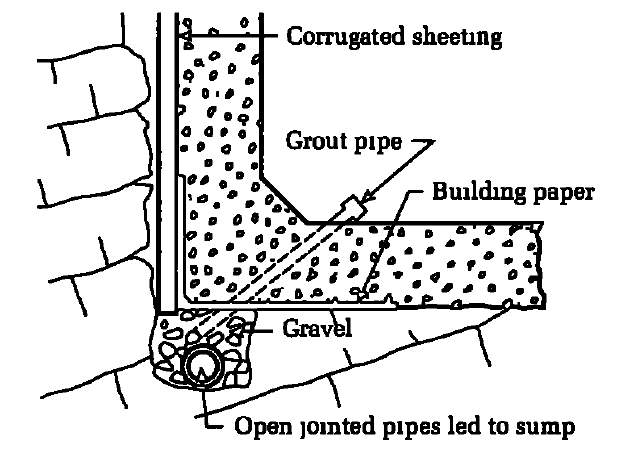
After the concrete work is completed, the area behind the sheeting is grouted using the pipes left for this purpose. Typically, occasional weeping can be remedied by plastering with quick-setting cement mixtures or by applying dry cement to the face prior to pouring concrete.
Calculation of rates of seepage of water into excavations
In large excavations, it is necessary to estimate the amount of water that must be pumped in order to remove the water from below the formation level. This quantity must be known in order to provide the required number and capacity of pumps. In the case of long-relative-to-width trench excavations, the flow calculation can typically be modelled as a condition of gravitational flow to a partially penetrating slot (Figure 5).
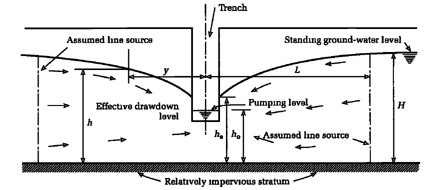
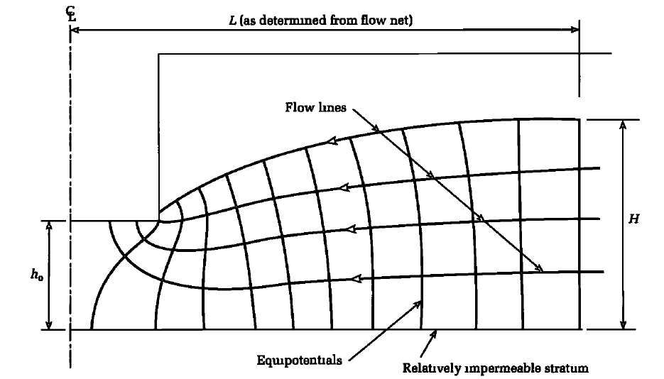
For this flow condition, ground water in the pervious layer is not confined by an impervious layer above it, and the trench does not extend completely through the pervious water-bearing layer. In addition, the source of ground water is distant from the excavation, as there is no large body of water such as a river or the ocean nearby.
For the conditions in Figures 5 and 6, flow to the trench from both sides of the excavation is given by the equation;
q = [0.73 + 0.27(H – h0)/H] k/L(H2 – h02) ——— (1)
where;
q = quantity of flow per unit length of trench,
k = coefficient of permeability of the pervious layer,
H, h0, and L are dimensions as shown in Figure 5.
The dimension L can be obtained by drawing a flow net as shown typically in Figure 6 or approximately by substituting L for R0 in equation (5) (see below). Where the draw-down (H — h) has been measured in a trial excavation at a distance y from the slot, L can be obtained from the equation;
H2 — h2 = (L – y)/L (H2 – hc2) ——— (2)
Where the trench penetrates fully the water-bearing layer, the flow to the trench from both sides of the excavation is given by the equation;
q = k/L(H2 – hc2) ——— (3)
If there is a large body of water such as the sea or a river close to one side of the excavation, the flow to the opposite side from a remote source of water will be small in comparison with that to the side close to the line source and it can be neglected. The flow from the nearby source, assuming this to be a line source of infinite length compared to the length of the trench, is equal to half the quantity as calculated by either equations (1) or (3), and the distance L is the distance from the trench to the nearby source.
Where a pumping test has been made in the excavation and the draw-down (H — h) is measured at a radius r from the well, the dimension R0 for gravity flow can be calculated from the equation;
H2 — h2 = [(H2 — hw2)/loge(R0/rw)] × loge(R0/r) ——— (4)
Alternatively R0 can be obtained by drawing a flow net or it can be obtained approximately from the empirical equation.
R0 = CH√k ——— (5)
where;
C = a factor equal to 3000 for radial flow to pumped wells and between 1500 and 2000 for line flow to trenches or to a line of well points,
H = total draw-down in metres,
k = coefficient of permeability in metres per second
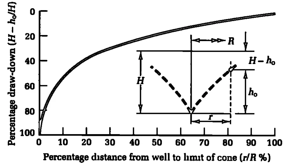
Shape of Draw Down Curve
It is often necessary to determine the shape of the drawdown curve to a well, for example to assess the risk of settlement of existing structures near the excavation. The draw-down in uniform soils can be obtained by means of Figure 7.
In the case of large rectangular or irregularly shaped excavations, the flow can be calculated by drawing a plan flow net of the type shown in Figure 8, when for gravity flow to a fully penetrating excavation the flow per unit thickness of the pervious layer is given by the equation;
q = k(H – he) × (Nf / Ne) ——— (6)
or for a thickness D of pervious water-bearing soil, the total flow to the excavation is given by;
Q = k(H – he) × D(Nf / Ne) ——— (7)
where;
k = coefficient of permeability,
Nf = number of flow lines,
Ne = number of equipotential lines
Worked Example
The plan flow net for a gravity flow to fully penetrating excavation for dry dock is shown below. For the example, H = 12.0 m, hc = 0, k = 8 × 10⁻⁴ m/s, D = 12.0 m, Nf = 14, Ne = 5
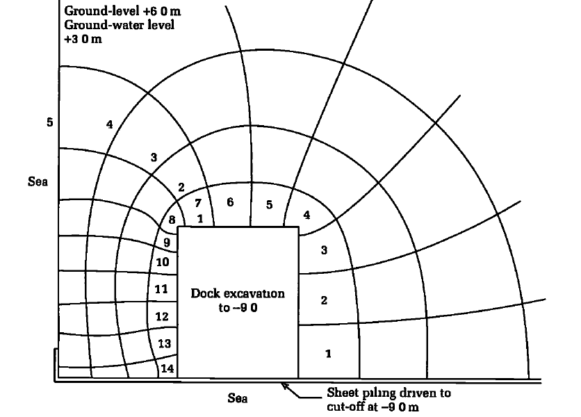
Therefore
Q = 8 × 10-4 × (12 — 0) × 12 × (14/5) = 0.32 m3/s or 19200 litres/min
It is important to note that the equations generated above are for the quantity of flow when stead state conditions have been obtained. A higher pumping capacity will be required in large and deep excavations if the time required to achieve the necessary draw down is not to be unduly protracted. The volume of water to be pumped out from standing water level to full draw down conditions in the excavation should be calculated and divided by the time required by the construction programme. This will give the initial pumping capacity to achieve the required draw down.
References
Tomlinson M. J. (2001): Foundation Design and Construction (7th Edition). Pearson Education




You should always have the knowledge of the soil and groundwater conditions before you start an excavation. The soil and groundwater conditions will determine the stability of the sides of your excavation and how deep you can excavate without encountering water. Good post!
This blog post on the seepage of water into excavations was an eye-opening read for me! As someone who once worked on a construction site near a river, I remember the frustration and concern caused by unexpected water infiltration. It was a constant battle to prevent water from flooding the excavation, and the practical tips shared in this post would have been a lifesaver back then. Kudos to the author for shedding light on this crucial aspect of construction!