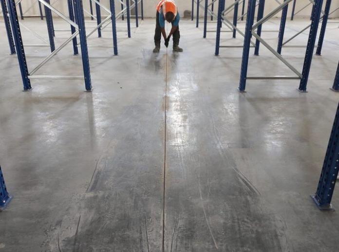
Due to the poor tensile strength of concrete, some degree of cracking in reinforced concrete is inevitable. Contraction joints are designed to create predetermined weak points where cracks can develop. The weakened section at a contraction joint can be created through forming or sawing, either with no reinforcement or by allowing a portion of the total reinforcement to pass through the joint. Through careful architectural planning, these joints can be strategically placed to ensure that any resulting cracks are less noticeable within a building and ideally out of plain view.
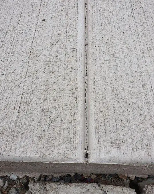
There are two primary reasons for controlling cracks in reinforced concrete buildings. Firstly, aesthetics play a significant role; visible cracks are unsightly, particularly when the concrete is intended to be the final finished product. Cracks in major structural elements like girders and columns can raise concerns about the structure’s structural integrity, even if they don’t necessarily pose a structural risk. Secondly, cracks of significant width can allow air and moisture to penetrate the structure’s framework, potentially causing durability issues.
As a result, there is a genuine need for crack control in reinforced concrete structures. The main questions revolve around how to manage the extent of cracking, achieved through contraction joints, and how to restrict stresses in members to an acceptable level, accomplished through expansion joints.
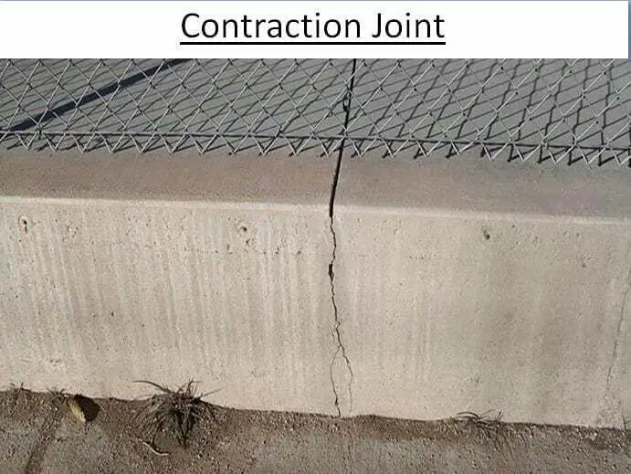
The following sections offer recommendations for contraction joint spacing. Once the joint locations are chosen, it’s crucial to construct the joint in a manner that fulfils its intended purpose.
Contraction Joints
Drying shrinkage and variations in temperature result in tensile stresses within a concrete mass, especially when the material is restrained. Cracks will develop when these tensile stresses exceed the tensile strength of the concrete, which is relatively low.
Given this inherent limitation of concrete, cracking of concrete sections is usually quite likely. Contraction joints serve as predetermined weak points where cracks can form without adversely affecting the overall appearance of a structure. Typically, contraction joints are primarily employed in walls and slabs-on-grade.
It’s important to note that the greater the spacing between contraction joints, the more significant the forces generated within a structure due to volume changes. To withstand these forces and minimize the extent of cracking in the concrete, additional reinforcement is needed.
Joint Configuration
Contraction joints are normally constructed as concrete sections with reduced cross-sectional area and reinforcement. To ensure the weakness of the section is sufficient for crack formation, it is recommended that the concrete cross-section be reduced by at least 25 percent. In terms of reinforcement, there are currently two types of contraction joints in use, referred to as “full” and “partial” contraction joints according to ACI 350R guidelines.
Full contraction joints, the preferred choice for most building construction, are established with a complete disruption in reinforcement at the joint. All reinforcement is terminated approximately 2 inches (51 mm) away from the joint, and if the joint serves as a construction joint, a bond breaker is placed between successive placements.
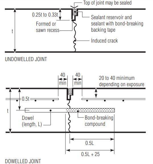
Partial contraction joints, on the other hand, are constructed with no more than 50 percent of the reinforcement passing through the joint. Partial contraction joints find application in liquid containment structures. In both types of joints, water stops may be employed to ensure water tightness.
Joint Location
Once the decision to employ contraction joints is made, the next consideration is determining the necessary spacing to control the extent of cracking between these joints. As detailed in Table 1, various recommendations are provided for contraction joint spacing. The suggested spacings range from 15 to 30 feet (approximately 0.6 to 9.2 meters) and from one to three times the height of the wall.
| Author | Recommended contraction joint spacing |
| Merrill (1943) | 20 ft (6 m) for walls with frequent openings, 25 ft (7.5 m) in solid walls. |
| Fintel (1974) | 15 to 20 ft (4.5 to 6 m) for walls and slabs on grade. Recommends joint placement at abrupt changes in plan and at changes in building height to account for potential stress concentrations. |
| Wood (1981) | 20 to 30 ft (6 to 9 m) for walls |
| PCA (1982) | 20 to 25 ft (6 to 7.5 m) for walls depending on number of openings. |
| ACI 302.1R | 15 to 20 ft (4.5 to 6 m) recommended until 302.1R-89, then changed to 24 to 36 times slab thickness. |
| ACI 350R-83 | 30 ft (9 m) in sanitary structures. |
| ACI 350R | Joint spacing varies with amount and grade of shrinkage and temperature reinforcement. |
| ACI 224R-92 | One to three times the height of the wall in solid walls |
For sanitary structures, Rice (1984) offers contraction joint spacings based on specific reinforcement percentages (as outlined in Table 2).
| Contraction joint spacing in ft. | Minimum percentage of shrinkage and temperature reinforcement (fy = 276 MPa) | Minimum percentage of shrinkage and temperature reinforcement (fy = 413 MPa) |
| less than 30 | 0.30 | 0.25 |
| 30 – 40 | 0.40 | 0.30 |
| 40 – 50 | 0.50 | 0.38 |
| greater than 50 | 0.60 | 0.45 |
It’s important to note that the limits specified by Rice in Table 2 extend the recommendations outlined in ACI 350R, taking into account factors such as reinforcement grade and minimum bar size. It’s worth mentioning that when employing a “partial” contraction joint, the spacing should be roughly two-thirds of that used for a full contraction joint, as per ACI 350R guidelines.
Additionally, Wood (1981) suggests that any joint within a structure should traverse the entire structure in a single plane. Misalignment of joints may result in movement at one joint causing cracking in an unjointed portion of the structure until the crack intersects another joint.
For slabs-on-grade and concrete pavements, contraction joints are usually placed at depths ranging from 1/4 to 1/3 of the slab’s thickness and are commonly spaced at intervals of 3.1 to 15 meters (approximately 12 to 50 feet). Thinner slabs tend to have more closely spaced joints. According to the Portland Cement Association (PCA), contraction joints are spaced at intervals ranging from 24 to 30 times the thickness of the slab. When the spacing between joints exceeds 15 feet (4.5m), the inclusion of load transfer mechanisms such as dowels or diamond plates becomes necessary.
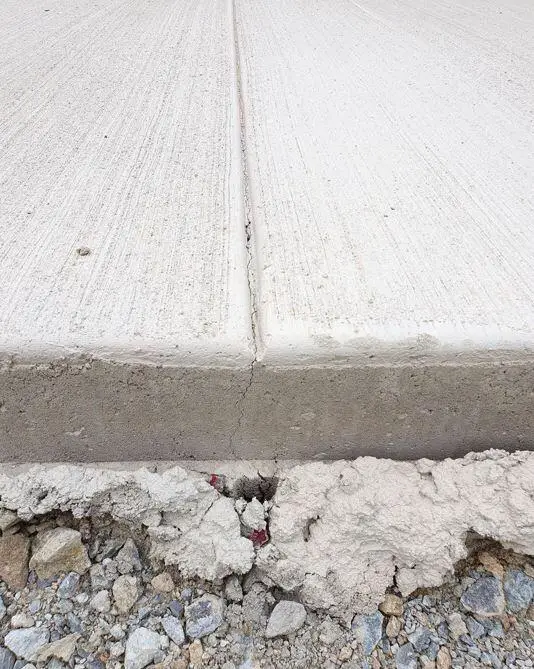
It is also common to have, a semi-random pattern for joint spacing in pavements to reduce their impact on vehicle resonance. Such patterns often involve a recurring sequence of joint spacings, such as 2.7 meters (9 feet), followed by 3.0 meters (10 feet), then 4.3 meters (14 feet), and subsequently 4.0 meters (13 feet).
Conclusion
In conclusion, contraction joints play an important role in the construction of concrete structures. These strategically placed joints serve as planned weak points, allowing for controlled cracking in response to factors like temperature variations and drying shrinkage. Properly designed and spaced contraction joints are essential for maintaining the structural integrity and aesthetic appeal of buildings and other concrete structures.
The choice of joint type, spacing, and reinforcement is crucial, as it directly impacts the extent of cracking and the overall durability of the structure. By adhering to recommended guidelines and considering the specific needs of the project, engineers and builders can effectively manage and control cracking, ensuring that the structure remains safe, functional, and visually pleasing for years to come.
References
ACI Committee 224, “Control of Cracking in Concrete Structures,” ACI 224R-80, Concrete International, V. 2, No. 10, Oct. 1980, pp. 35-76.
ACI Committee 302, “Guide For Concrete Floor and Slab Construction (ACI 302.1R-89),” American Concrete Institute, Detroit, 1989, 45 pp.
ACI Committee 318, “ACI Standard Building Code Requirements for Reinforced Concrete (ACI 318-63),” American Concrete Institute, Detroit, 1963, 144 pp.
ACI Committee 350, “Concrete Structures (ACI 350R83),” American Concrete Institute, Detroit, 1983, 20 pp.
Fintel, M. (1974). “Joints in Buildings,” Handbook of Concrete Engineering, New York, Van Nostrand Reinhold Company, 1974, pp. 94-110.
Merril, W. S. (1943). “Prevention and Control of Cracking in Reinforced Concrete Buildings,” Engineering News-Record, V. 131, No. 23, Dec. 16, 1943, pp. 91-93
Rice, P.F. (1984). “Structural Design of Concrete Sanitary Structures,” Concrete International, V. 6, No. 10, Oct. 1984, pp. 14-16.
Wood, R. H. (1981). “Joints in Sanitary Engineering Structures,” Concrete International, V. 3, No. 4, April 1981, pp. 53-56.

