Except where they join other structures, concrete pavements and industrial floors should ideally be free of joints. However, joints in concrete pavements are usually provided for a variety of reasons, including construction considerations, reducing the possibility of unanticipated shrinkage cracking, and avoiding conflict with adjacent structures and/or penetrations. The number of joints in concrete pavements should be kept to a minimum because they not only affect the evenness of the pavement in most cases, but they are also the most prone to wear and require repairs.
The type of joint, joint configuration, sealant required, and quantity of reinforcement employed in the pavement panels are all interconnected. For example, increasing the amount of reinforcement allows for wider joint spacing, but it also means that the joints will move more, increasing the possibility of random cracking inside the pavement panels.
Load Transfer Across Joints in Concrete Pavements
Load transfer mechanisms like dowels can be utilized to transfer loads across a joint to adjacent pavement panels, resulting in lower flexural stresses in the panel than at free edges with no effective load transfer. They also prevent stepping by preventing differential vertical movements of adjacent concrete floor panels.
Aggregate interlock over the rough crack faces, keyed joints, dowels, or a combination of these can enable load transfer in contraction joints. If the opening is greater than 0.9 mm, as is common when panel lengths exceed 3 m, load transfer by aggregate interlock or keyways may become ineffective, and either an effective load-transfer device for these situations should be installed, or the base thickness for a free-edge condition should be determined.
According to ACI 302.1, the base thickness of dowels should be at least 125 mm to be fully functional. It also suggests using dowels for load transfer across joints, because regulating the differential vertical movement across joints can help prevent slab edge damage from vehicles with harsh wheels, such as forklifts.
Types of Joints in Concrete Pavements
Pavement construction uses four different types of joints:
- Isolation Joints
- Expansion joints
- Contraction Joints
- Construction joints
Isolation Joints
These joints allow for horizontal and vertical movement as well as rotation between abutting pieces, allowing them to function independently. They should be installed between a pavement panel and the building’s fixed components (such as columns, walls, machinery bases, pits, etc).
To avoid the buildup of stresses due to differential movements, isolation joints should be provided at the junction when an existing pavement is being extended, as well as at connections between internal and external pavements. Typically, load transmission between the existing pavement and the pavement extension will be required in the design.
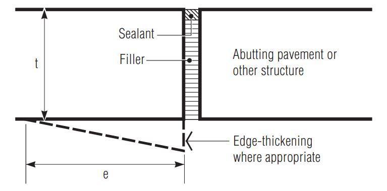
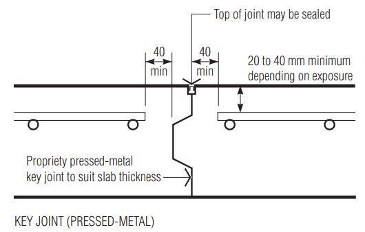
To ensure a complete separation, isolation joints in concrete pavements are often formed by casting against a compressible, prepared filler material (e.g., self-expanding cork) over the full depth of the joint. If loads are predicted to occur close to an isolation joint, the base edges adjacent to these joints may need to be thickened due to the edge loading condition. Figure 1 shows the typical characteristics of this type of joint. Note that the sealant should be applied to both the top and free edges of the joint to keep dirt and other incompressible materials out of the joint, preventing or restricting movement.
Expansion Joints
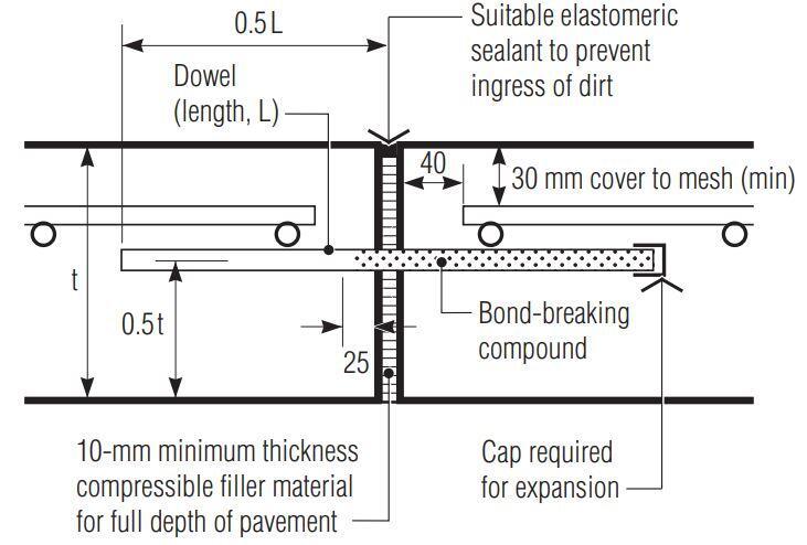
Pavements feature expansion joints to allow for temperature and moisture-induced movement of the base. These joints may, however, be required in places with significant temperature changes. Figure 2 shows the typical details of this type of joint. Note that the sealant should be applied to both the top and free edges of the joint to keep dirt and other incompressible materials out of the joint, preventing or restricting movement.
Internal floors do not require expansion joints because they do not experience severe temperature variations. Internally, the expansion due to heat movement is usually less than the concrete’s initial shrinkage. Even the thermal movement of a cold-store floor will not be greater than the floor’s original shrinkage. In interior applications, AS 3600 recommends design shrinkage values of 670 x 10–6 for 200-mm-thick slabs and 450 x 10–6 for 400-mm-thick slabs.
According to TR 35, the overall shrinkage coefficient for pavements is around 300 x 10–6. With a coefficient of thermal expansion of 10 x 10–6/°C, an expansion equal to the drying shrinkage would require a temperature of around 30°C above the putting temperature. As a result of the lack of thermal ranges in industrial floors, expansion joints are not necessary.
Furthermore, if drying shrinkage is ignored and the restraint to slab lengthening due to temperature rise and/or moisture increase is ignored, the maximum compressive strain in the concrete will be 300 x 10–6 for a temperature rise of 30°C above the placing temperature (and the slab moisture content returns to saturation), assuming no expansion joints are provided. Assuming f’c = 40 MPa, Ec is 31975 MPa, while the compressive stress is 9.6 MPa. The absence of expansion joints in industrial floors is supported by this minimal compressive stress development.
Designers should determine whether expansion joints are necessary inside before specifying their use, as the required joint width will necessitate additional considerations.
To reduce forklift vehicle wear and accompanying high maintenance costs, treatment (armouring of joint edges) is used. Expansion joints in concrete pavements also necessitate the use of load transfer devices, such as dowels, bars, or plates, due to the separation of adjacent panels. Whenever expansion joints are not provided, alternative joints within the pavement should be sealed to avoid the intrusion of incompressible material, which could limit subsequent floor expansion.
Contraction Joints
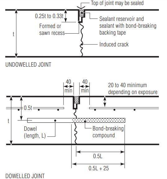
The random drying shrinkage cracking of concrete is controlled by contraction or control joints, which cause the base to crack exclusively at the joint positions. They allow the base to move horizontally at right angles to the joint, relieving pressures that could otherwise induce random cracking. A plane of weakness is generated by shaping (with crack-inducing tapes or formers) or cutting a groove to a depth of one-quarter to one-third of the base thickness to ensure that shrinkage cracking develops at a contraction joint. Figure 3 shows the typical details.
However, if the groove is created early enough using an appropriate grooving tool or early-age saw cutting, the groove depth can be reduced in concrete slabs that are either plain or reinforced (mesh).
The spacing of contraction joints in jointed unreinforced pavements should be chosen to suit the shape of the pavement while ensuring that load transfer by aggregate interlock is not compromised. If this is the case, load transfer must be accomplished through other means, or the base thickness should be built as a free edge.
Contraction joints are commonly made by cutting a groove in the top of freshly laid concrete (Formed Joint) or by sawing the concrete after it has set but before it cracks uncontrollably (Sawn Joint).
Formed Joints
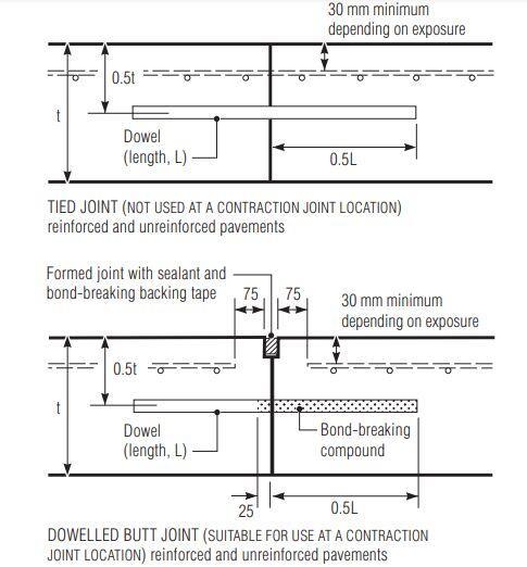
Forming a groove with a T-section and edge tools or inserting a prepared crack inducer into the surface while the concrete is still plastic can be used to produce formed joints. After the pavement has been completed, a sealer can be put in the contraction joints by applying an appropriate sealant reservoir and bond-breaking backing tape. The reinforcement in reinforced pavements must not obstruct the created joint. Figure 4 shows how the reinforcement could be terminated short of the joint.
Sawn Joints
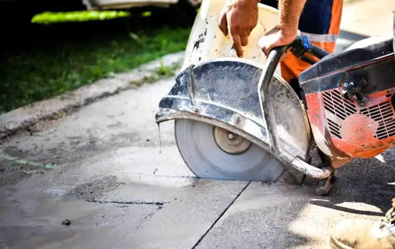
Sawn joints are constructed just after the concrete has hardened enough that the sawing will not damage it but before shrinkage cracking develops (see Figure 5). The best time to saw depends on a variety of factors that influence concrete hardening, such as concrete strength and ambient temperature. The depth of the initial saw cut should be 3 to 5 mm. The joint can be enlarged later if necessary for the installation of a joint sealer.
When using dowels, it is important to ensure that they don’t get in the way of the joint’s opening or closing; otherwise, an uncontrolled crack could form in the joint’s surroundings. Round or square dowels cut on both ends, for example, should not be utilized because the end deformation may interfere with the joint opening or closing. Dowels should be coated with a suitable bond breaker on one side of the joint and aligned to within close tolerances parallel to the longitudinal direction of the panel and the surface of the base.
Diamond-shaped load plates can be used to replace dowels and allow the slab to travel horizontally without restraint; they also allow some differential movement in the joint’s direction, especially when shrinkage opens the joint. They can be placed within 150 mm spacings, whereas dowels should be kept at a distance of 300 mm. It is worth noting that dowels near crossings need to have expansion material on the vertical sides to allow the slab to move both parallel and perpendicular to the connection. Square dowels will almost always be required for this.
Individual panels in jointed reinforced pavements are usually joined by construction, expansion, or isolation joints, rather than contraction joints. Joint spacing should be limited to roughly 15 m for these pavements so that joint movement does not become excessive and joint sealing remains effective.
Construction Joints
Longitudinal construction joints separate portions of concrete poured at different times and form the borders of each pour. Transverse construction joints are necessary at predetermined points, such as the end of each day’s work, and at unanticipated pauses, such as those induced by bad weather or equipment breakdowns.
Simple keyed joints will frequently suffice for longitudinal construction joints if the pavement is lightly loaded, not more than 150 mm thick, and built over a strong, unyielding subgrade that is not subject to volume variations, or over a bound subbase or stabilised subgrade. Longitudinal construction joints should be provided with some type of load-transfer mechanism, such as dowels or diamond load plates, if the pavement is thicker or more heavily loaded. Figure 6 shows typical details of this sort of joint.
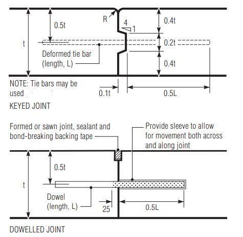
A keyed joint will not perform well as a load transfer device if it opens up more than 1 mm. When employing this type of joint for load transfer, it’s important to keep the joint opening to a minimum. Deformed tie bars can be used to hold keyed longitudinal joints together.
However, unless dowelled longitudinal contraction joints are additionally provided at a spacing not exceeding 15 m, such tie bars should not be utilized in panels having a total width of more than 15 m. Tie bars should be 800-mm length N12 bars with a spacing of 800 mm or 650000/DSj mm, whichever is lesser. Where D is the base thickness in millimeters and Sj is the joint spacing in millimeters (mm).
In reinforced pavement construction, using split or slotted formwork to ensure continuity of reinforcement across the junction can provide positive control against vertical movement at the joints. However, creating and removing the formwork presents construction challenges. The reinforcement must be planned for the entire length of the pavement, not just the panel length. In jointed unreinforced pavements, transverse construction joints should be placed where a planned contraction joint would be. Unplanned construction joints should be placed in the panel’s middle third. Figure 6 shows some typical details.
A dowelled butt joint, which allows horizontal movement and performs all of the duties of a contraction joint, is recommended when a transverse construction junction is intended to coincide with the place where a contraction joint would ordinarily occur Figure 1.5. Planned construction joints are often built at regular contraction joint sites in jointed reinforced pavements. Because there is no aggregate interlock to enable weight transfer, butt joints with dowels (perhaps also with expansion material) are recommended. The dimensions, spacing, and debonding of the dowels are the same as for a transverse contraction joint.
A transverse construction joint is made in continuously reinforced pavements by putting a special header board that allows reinforcing steel to pass through. Prior to resuming concrete placement, the header is removed. Both slotted and split header boards are utilized, but the slotted form is preferred since it can be removed with the least amount of disruption to the already cast concrete.
References
Cement Concrete & Aggregates Australia (2009): Guide to Industrial Floors and Pavements – design, construction and specification CCAA T48

