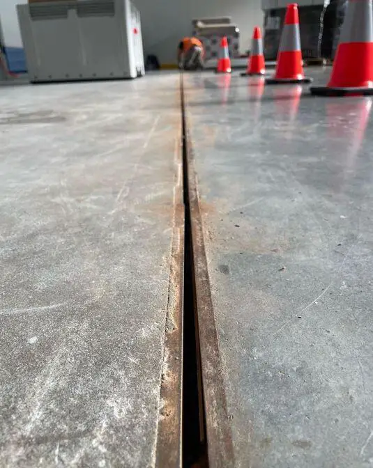
In the design of reinforced concrete buildings, it is essential to consider how changes in moisture and temperature can affect the volume of the structure. The magnitude of the stresses generated and the extent of the movement resulting from these volume alterations are directly related to the length of the building. To mitigate the effects of moisture or temperature-induced changes and prevent cracking, expansion joints are employed to divide buildings into distinct sections.
Expansion joints (also known as movement joints) are gaps in structures that allow different parts of the structure to move independently. They represent a disruption in both reinforcement and concrete, making them effective for accommodating both shrinkage and temperature variations. This is important because all materials expand and contract when their temperature changes. Without expansion joints, this movement could cause the structure to crack or fail.
This is especially true for building materials, such as concrete and steel, which can experience significant temperature changes throughout the day and year. Without expansion joints, these temperature changes would cause buildings to crack.

Joints in a building can serve as weak points to control crack locations (contraction joints) or create complete separation between segments (expansion joints). Currently, there is no universally agreed-upon design approach for accommodating building movements due to temperature or moisture variations. Many designers rely on “rule of thumb” guidelines that specify the maximum permissible distance between building joints.
Expansion joints are typically made of flexible materials, such as rubber or metal, which can compress and expand to absorb the movement of the structure. They are often sealed to prevent water and other elements from entering the structure.
The Need for Joints in Buildings
Expansion joints allow thermal expansions to occur in a building with minimal stress buildup. The greater the spacing between these joints, the higher the stresses they can accommodate. Typically, expansion joints divide a structure into segments, offering sufficient joint width to accommodate the building’s expansion as temperatures rise. In addition to mitigating contraction-induced cracking, expansion joints serve a dual purpose by providing relief from such cracking.
Controlling cracks in reinforced concrete structures is motivated by two main factors. Firstly, aesthetics are a significant consideration; noticeable cracks can mar the appearance, especially when the concrete is meant to be the final surface.
Cracks in crucial structural components like beams and columns can also lead to questions about the overall structural soundness, even if they don’t inherently jeopardize the building’s stability. Secondly, large crack widths can create pathways for air and moisture to infiltrate the structural framework, potentially leading to durability problems.
As a result, there is a genuine need for crack control in reinforced concrete structures. The main questions revolve around how to manage the extent of cracking, achieved through contraction joints, and how to restrict stresses in members to an acceptable level, accomplished through expansion joints.
Expansion Joints
Temperature changes induce stress within a structure, but this only occurs when the structure is restrained. In the absence of constraints, there are no resulting stresses. For instance, temperature difference has no effect on statically determinate structures.
In reality, almost all buildings have some level of restraint. The magnitude of temperature-induced stresses varies with the extent of temperature change; substantial temperature fluctuations can lead to significant stresses that must be considered during the design process, while minor temperature changes may result in negligible stresses.
These temperature-induced stresses occur due to changes in the volume of a structure between points where it is restrained. To estimate the amount of elongation caused by temperature increases, one can roughly multiply the coefficient of concrete expansion (approximately 12 x 10-6 /℃) by the length of the structure and the temperature change.
For example, a 200-foot-long building exposed to a temperature rise of 25 degrees Fahrenheit (14 degrees Celsius) will elongate by about 3/8 inch (9.5 millimetres). Expansion joints are employed to mitigate the forces imposed by thermally induced volume changes.
Expansion joints allow distinct sections of a building to expand or contract independently without negatively impacting its structural integrity or functionality. These joints should have sufficient width to prevent contact between portions of the building on either side of the joint when the structure experiences the maximum expected temperature rise.
The width of expansion joints can range from 1 to 6 inches or more, with 2 inches being the typical width. Wider joints are used to accommodate additional differential movement resulting from settlement or seismic forces. These joints should extend throughout the entire structure above the foundation level and can be either covered or filled. Filled joints are mandatory for fire-rated structures.

Spacing of Expansion Joints
There can be some debate about whether expansion joints should be included in building design and, if so, what spacing they should have. The spacing of expansion joints depends on the acceptable level of movement, as well as the allowable stresses and/or capacity of the structural elements. It also depends on the length and stiffness of frame members and the seasonal temperature fluctuations experienced at the construction site.
The design temperature change is calculated based on the difference between the extreme values of the daily maximum and minimum temperatures. In addition to general guidelines, various methods have been developed to calculate the appropriate spacing for expansion joints.
| Author | Spacing of expansion joint |
| Lewerenz (1907) | 75 ft (23 m) for walls. |
| Hunter (1953) | 80 ft (25 m) for walls and insulated roofs, 30 to 40 ft (9 to 12 m) for uninsulated roofs. |
| Billig (1960) | 100 ft (30 m) maximum building length without joints. Recommends joint placement at abrupt changes in plan and at changes in building height to account for potential stress concentrations |
| Wood (1981) | 100 to 120 ft (30 to 35 m) for walls. |
| Indian Standards Institution (1964) | 45 m (≈ 148 ft) maximum building length between joints |
| PCA (1982) | 200 ft (60 m) maximum building length without joints |
| ACI 350R-83 | 120 ft (36 m) in sanitary structures partially filled with liquid (closer spacings required when no liquid present). |
Similar to contraction joints, practical guidelines have been established, as outlined in Table 1. These guidelines vary depending on the type of structure and span a range of 30 to 400 feet (9 to 122 meters). In addition to these rule-of-thumb recommendations, several methodologies have been devised to determine the appropriate spacing for expansion joints. This section introduces three such methods, all rooted in the research conducted by Martin and Acosta in 1970, Varyani and Radhaji in 1978, and the National Academy of Sciences in 1974.
Some recommendations propose placing movement joints in masonry structures at approximately 7 meters apart, matching the spacing of the frame elements. For concrete floor slabs, the suggested spacing is approximately 20 to 30 meters, according to Deacon (1986), Bussell and Cather (1995), and the Concrete Society (2003). This implies that continuous multi-bay frames should also incorporate movement joints at similar intervals.
Consequently, a decision must be made: either incorporate movement joints throughout the entire height of the structure, necessitating full wind bracing in each portion of the structure or design the structure to withstand the forces generated by such movements.
Calculation of Expansion Joint Spacing (Single Storey Buildings)
In 1970, Martin and Acosta introduced a technique for determining the maximum allowable spacing between expansion joints in single-story frames with spans that are approximately equal. Their approach assumes that, with appropriate joint spacing, the load factors related to gravity loads will offer sufficient safety margins against the impact of temperature variations.
Martin and Acosta derived a unified formula to calculate the expansion joint spacing, denoted as “Lj,” which relies on the structural stiffness characteristics of the frame and the designated temperature change, ∆T. This equation was developed through a study of frame structures designed in accordance with ACI 318-63 standards. The formula for expansion joint spacing is as follows:
Lj = 112000/R∆T (inches)
∆T in Fahrenheit, or
Lj = 12.24/R∆T (metres)
∆T in degrees Celsius
In the above expressions:
R = 144 × (Ic/h2) × [(1 + r)/(1 + 2r)]
∆T = 2/3 (Tmax – Tmin) – Ts
where:
r = ratio of stiffness factor of column to stiffness factor of beam = Kc/Kb;
Kc = column stiffness factor = Ic/h, in.3(m3)
Kb = beam stiffness factor = Ib/L, in.3 (m3)
h = column height, in. (m)
L = beam length, in. (m)
Ic = moment of inertia of the column, in.4(m4)
Ib = moment of inertia of the beam, in.4 (m4)
Ts = 30 F (17 C)
Values for Tmax and Tmin can be obtained from the Environmental Data Service for a particular location. The design temperature change ∆T is based on the difference between the extreme values of the normal daily maximum and minimum temperatures. An additional drop in temperature of about 30 F (17 C) is then added to account for drying shrinkage.

Conclusion
In the construction industry, expansion joints play a critical role in ensuring the longevity, safety, and functionality of the building structures. Their design and placement require careful consideration of various factors, including temperature variations, structural movement, and material characteristics. By providing controlled gaps to accommodate movement and stresses, expansion joints can be used to create robust and resilient structures in the face of dynamic forces and environmental challenges.
References
ACI Committee 350, “Concrete Structures (ACI 350R83),” American Concrete Institute, Detroit, 1983, 20 pp
Billig, Kurt, “Expansion Joints,” Structural Concrete, London, McMillan and Co., Ltd., 1960, pp. 962-965.
Code of Practice for Plain and Reinforced Concrete, IS 456-1964, 2nd Revision, Indian Standards Institution, New Delhi, 1964
Hunter, L.E., “Construction and Expansion Joints for Concrete,” Civil Engineering and Public Works Review, V. 48, No. 560, Feb. 1953, pp. 157-158, and V. 48, No. 561, Mar. 1953, pp. 263-265.
Lewerenz, A.C., “Notes on Expansion and Contraction of Concrete Structures,” Engineering News, V. 57, No. 19, May 9, 1907, pp. 512-514
Wood, Roger H., “Joints in Sanitary Engineering Structures,” Concrete International, V. 3, No. 4, April 1981, pp. 53-56.


