If you missed the PART 1 of this post, click HERE
Problem 1
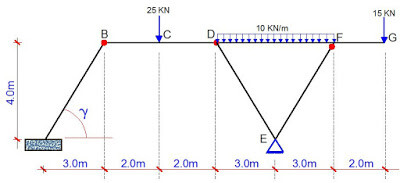
A statically determinate frame is loaded as shown above. There are internal hinges at B and D, while member EF is hinged at point F. Draw the bending moment, the shear force, and the axial force diagrams.
SOLUTION
Notations
MiR – Bending moment at point i, just to the right
MiL – Bending moment at point i, just to the left
QiR – Shear force at point i, just to the right
QiL – Shear force at point i, just to the left
(a) Support Reactions
Let ∑ME = 0 (clockwise positive)
10Ay + MA – (25 × 5) – [(10 × 32) / 2) + [(10 × 32) / 2) + (15 × 5) = 0
10Ay + MA = 50 ————– (1)
Let ∑MDL = 0 (clockwise positive)
7Ay + MA – 4Ax – (25 × 2) = 0
7Ay + MA – 4Ax = 50 ————— (2)
Let ∑MBBelow = 0 (clockwise positive)
3Ay + MA – 4Ax = 0
3Ay + MA– 4Ax = 0 ————— (3)
From equation (1);
MA = 50 – 10Ay —————— (1a)
Substituting the value of MA in equation (1a) into equations (2) and (3), we obtain respectively;
7Ay – 4Ax + 50 – 10Ay = 50
– 3Ay – 4Ax = 0 ————– (4)
3Ay + 50 – 10Ay – 4Ax = 0
– 7Ay – 4Ax = – 50 —————– (5)
Solving equations (4) and (5) simultaneously;
Ay = 12.5 KN
Ax = – 9.375 KN
Hence;
MA= 50 – 10(12.5) = – 75 KNm
At this point, it is very possible for us to sum up vertical and horizontal forces in order to obtain the rest of the reactive forces, but let us still obtain them by taking moments (this is very useful since it can serve as a check for correctness of results).
Let ∑MDR = 0 (anticlockwise positive)
3Ey – 4Ex – (15 × 8) – (10 × 6 ×3) = 0
3Ey – 4Ex = 300 —————- (6)
Let ∑MBR = 0 (anticlockwise positive)
7Ey – 4Ex – (15 × 12) – (10 × 6 ×7) – (25 ×2) = 0
7Ey – 4Ex = 650 —————– (7)
Solving equations (6) and (7) simultaneously;
Ey = 87.5 KN
Ex = – 9.375 KN
Equilibrium check;
∑Fy↓ = 25 + (10 × 6) + 15 = 100 KN
∑Fy↑ = 12.5 + 87.5 = 100 KN
This shows that the requirement for static equilibrium is satisfied,. You can also verify for the horizontal reaction at the supports.
Before we go ahead and obtain the bending moment and shearing forces, let us obtain the axial forces in members DE and DF. Since they are pinned at both ends, they are primarily trusses and will not develop any bending moment or shear force.
γ = tan(-1)(4/3) = 53.130°
cos γ = 0.6
sin γ = 0.8
∑Fy = 0
87.5 + FEDsin γ + FEFsinγ = 0
0.8FED + 0.8FEF = – 87.5 —————– (8)
∑Fx = 0
9.375 – FEDcos γ + FEFcosγ = 0
-0.6FED + 0.6FEF = – 9.375 ——————- (9)
Solving equations (8) and (9) simultaneously;
FED = – 46.875 KN (compression)
FEF = – 62.5 KN (compression)
These forces are now resolved into their vertical and horizontal components at the points they are attached to the beam as shown below;
(b) Internal Stresses
MEMBERAB (0 ≤ z ≤ 5)
Bending Moment
Mz = (Ay.cosγ.z) – (Ax.sinγ.z) – MA
Mz = (12.5 × 0.6 × z)- (-9.375 × 0.8 × z) – 75 = 15z – 75
At z = 0;
MA = -75 KNm
At z = 5m
MBBelow = 15(5) – 75 = 0
Shear Force
Qz = (Ay.cosγ) – (Ax.sinγ)
Qz = (12.5 × 0.6) – (-9.375 × 0.8) = 15 KN (constant shear force all through the member)
Axial Force
Nz = – (Ay.sinγ) – (Ax.cosγ)
Qz = – (12.5 × 0.8) – (-9.375 × 0.6) = – 4.375 KN (constant axial force all through the member)
MEMBER BD (3 ≤ x ≤ 7)
Bending Moment
The general moment equation for the member is given by;
Mx = Ay.x + (Ax × 4) – MA – 25(x – 5)
Mx = 12.5x + (9.375 × 4) – 75 – 25(x – 5)
Mx = 12.5x – 37.5 – 25(x – 5)
You can however notice that for section BC, the last term of the general equation will not be involved since we cannot have a negative distance on the beam. Therefore it is not very wise to expand the equation yet.
At x = 3m;
MBR = 12.5(3) – 37.5 = 0
At x = 5m;
MC = 12.5(5) – 37.5 – 25(5 – 5) = 25 KNm
At x = 7m;
MD = 12.5(7) – 37.5 – 25(7 – 5) = 0
Shear Force
QBR – QCL = 12.5 KN
You can verify that the valid equation for moment at the section (BR – CL) is given by;
Mx = 12.5x – 37.5
If we differentiate the equation for moment, we obtain the equation for shear;
(∂Mx)/∂x = Qx = 12.5 KN
You can also verify that the valid equation for moment at the section (CR – DL) is given by;
Mx = 12.5x – 37.5 – 25(x – 5) = -12.5x + 87.5
(∂Mx)/∂x = Qx = -12.5 KN
Hence, QCR – QDL = -12.5 KN
Axial Force
You can verify that for section BR – DL
NB – Ax = 0
Hence NB = 9.375 KN (tension)
MEMBER DF (7 ≤ x ≤ 13)
Bending Moment
Mx = Ay.x + (Ax × 4) – MA – 25(x – 5) + 37.5(x – 7) – [10(x – 7)2) / 2
Mx = 12.5x + (9.375 × 4) – 75 – 25(x – 5) + 37.5(x – 7) – [10(x – 7)2) / 2
Mx = 12.5x – 37.5 – 25(x – 5) + 37.5(x – 7) – 5(x – 7)2
At x = 7m;
MBR = 12.5(7) – 37.5 – 25(7 – 5) = 0
At x = 10m (mid-span);
Mmid = 12.5(10) – 37.5 – 25(10 – 5) + 37.5(10 – 7) – 5(10 – 7)2 = 30 KNm
At x = 13m;
MFL = 12.5(13) – 37.5 – 25(13 – 5) + 37.5(13 – 7) – 5(13 – 7)2 = – 30 KNm
Shear Force
You can verify that the valid equation for moment at section D just to the right (DR) is;
Mx = 12.5x – 37.5 – 25(x – 5) + 37.5(x – 7) = 25x – 175
(∂Mx)/∂x = QDR = 25 KN
The valid equation for moment at section F just to the left (FL) is;
Mx = 12.5x – 37.5 – 25(x – 5) + 37.5(x – 7) – 5(x – 7)2
Mx = 12.5x – 37.5 – 25x + 125 + 37.5x – 262.5 – 5(x2 – 14x + 49)
Mx = -5x2 + 95x – 420
(∂Mx)/∂x = Qx = -10x + 95
Maximum span moment
The maximum moment at the span can be obtained by considering the bending moment equation unique for the section.
Mx = -5x2 + 95x – 420
(∂Mx)/∂x = Qx = -10x + 95
Since the maximum moment occurs at the point of zero shear, let us equate the expression for the shear force to zero, and then solve for x;
Such that x = 95/10 = 9.5m
Mmax = -5(9.5)2 + 95(9.5) – 420 = 31.25 KNm
At x = 13m;
QFL = -10(13) + 95 = -35 KN
Axial Force
For section DL – FR
N – Ax – 28.125 = 0
Hence N = 9.375 + 28.125 = 37.5 KN (tension)
MEMNER FG (coming from the right for simplicity) (0 ≤ x ≤ 2m)
Bending Moment (clockwise negative)
Mx = -15x
At x = 0;
MG = 0 KNm
At x = 2m
MFR = -15(2) = – 30 KNm
Shear Force
QGL – QFR = 15 KN (downward force is positive when coming from the right)
Axial Force
No axial force in the member
Final Internal Stresses Diagram
To download this calculation sheet in printable PDF format for free, click HERE
For more structural analysis and design works, continue to visit;
Like us www.facebook.com/structville


