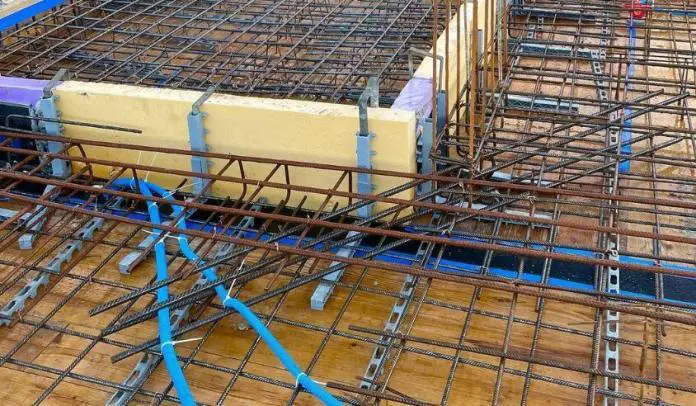
Structural detailing is the process of interpreting design information and instructions using drawings and schedules. In reinforced concrete slabs and other structures, detailing entails using drawings and schedules to specify the dimensions and arrangement of structural members, material properties, clear cover, reinforcement sizes, spacings, and arrangement.
It is the duty of the Designer and the Detailer to ensure that the information provided in the drawing is correct since the same will be used for execution on site. The essence of this article is to provide information on the detailing standards for reinforced concrete slabs according to the requirements of the Eurocodes and UK practice.
Detailing Information
The design information that should be provided in the detailing of reinforced concrete slabs include:
- Layout and section drawings including details of holes and upstands, etc.
- Concrete grade and aggregate size (minimum standard 25/30 MPa and 20mm).
- Nominal cover to reinforcement and controlling design consideration, fire or durability (standard 20mm for internal conditions 40mm for external conditions).
- Main reinforcement bar runs and positions. This should include:
- diameter, pitch of bars, and location (e.g. T1, T2, B1, B2, etc.)
- type of reinforcement and bond characteristics (standard: H)
- fixing dimensions to position bar runs and ends of bars.
- Details of any special moment bars connecting slab to wall or column.
- Details of cut-off rules, if other than standard shown in Model Details.
- Details of fabric required. For coffered slabs, this should include the fabric required in the topping and in the bottom of solid sections around columns. Sufficient details should be given to show that the reinforcement will fit in the depth available allowing for laps in the fabric. Guidance should be given for the additional area required for laps otherwise 22% will be assumed for 300mm laps.
- Details of insertions, e.g. conduit, cable ducting, cladding fixings, etc., should be given where placing of reinforcements is affected.
The Minimum Area of Reinforcement for Solid Slabs
According to Clauses 9.3.1.1, 9.3.1.2 and 9.2.1.1 of EC2;
- Tension reinforcement:
- As,min = 0.26btdfctm/fyk ≥ 0.0013btd where:
- bt is the mean width of the tension zone
- d is the effective depth
- fctm is determined from Table 3.2 of EC2
- fyk is the characteristic yield strength
- As,min = 0.26btdfctm/fyk ≥ 0.0013btd where:
- This also applies to nominal reinforcement.
- Minimum bottom reinforcement in direction of span: 40% of the maximum required reinforcement.
- Minimum top reinforcement at support (e.g. where partial fixity exists): 25% of the maximum required reinforcement in span, but not less than As,min. This may be reduced to 15% for an end support.
- Secondary transverse reinforcement: 20% of main reinforcement except where there is no transverse bending (e.g. near continuous wall supports).
- Preferred minimum diameter of reinforcement for solid slabs: 10mm.
The area of bottom reinforcement provided at supports with little or no end fixity assumed in design should be at least 0.25 that provided in the span.
Bar spacing
According to Clauses 8.2 and 9.3.1.1 of EC2, the recommended minimum spacing of reinforcing bars is 75 mm and 100 mm for laps.
Maximum spacing of bars for slabs
• Main bars: 3h ≤ 400mm (in areas of concentrated loads 2h ≤ 250mm)
• Secondary bars: 3.5h ≤ 450mm (in areas of concentrated loads 3h ≤ 400mm)
Where h is the thickness of the slab.
Anchorage and Lapping of Bars
For high yield and 500 Grade steel, the table below gives typical anchorage and lap lengths for ‘good’ and ‘poor’ bond conditions. For ends that are on ‘direct supports’ the anchorage length beyond the face of the support may be reduced to d but not less than the greater of 0.3 lb,rqd, 10b or 100mm.
Table 1: Typical anchorage and lap length for solid slabs

Where loading is abnormally high or where point loads are close to the support, reference should be made to EC2, Sections 8 and 9. Lap lengths provided (for nominal bars, etc.) should not be less than 15 times the bar size or 200 mm, whichever is greater. The arrangement of lapped bars should comply with Figure 1;
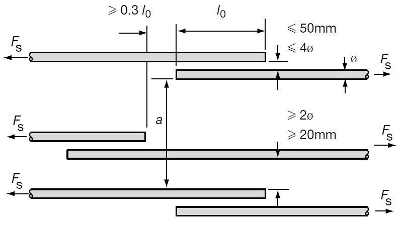
Simplified Curtailment Rules for Reinforcement
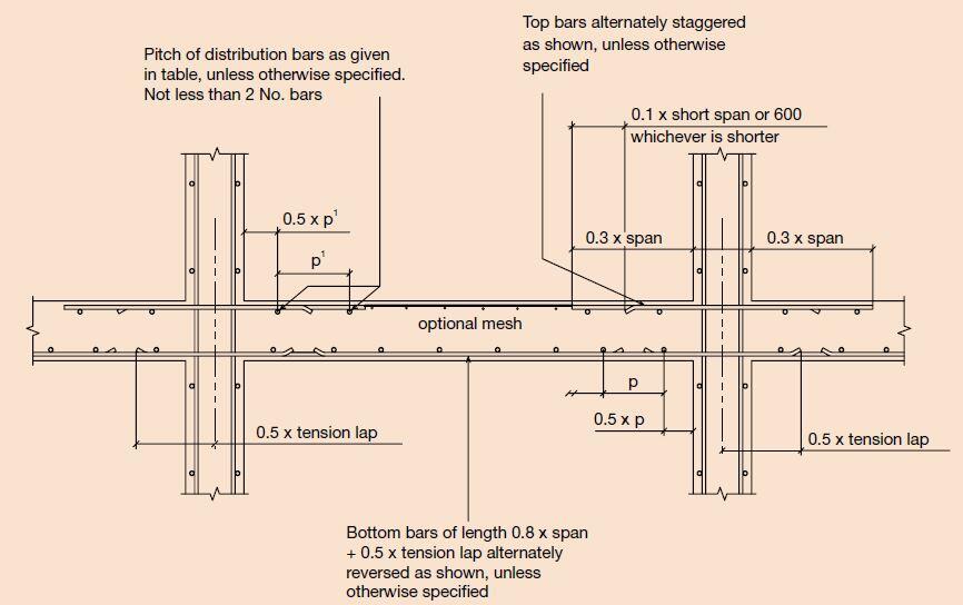
When only the minimum percentage of reinforcement is provided, there should be no curtailment when detailing reinforced concrete slabs. Simplified rules for curtailment of bars may be used without bending moment diagrams, provided adjacent spans are approximately equal (within 15%) and provided that the loading is uniformly distributed. The simplified rules for curtailment in solid slabs can be seen in Figures 2 to 5.
At internal supports in one-way and two-way slabs, the top reinforcement should extend into the span by 0.3 x times the length of the span as shown in Figure 2.
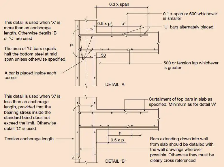
When the end support of a solid one-way or two-way slab is completely restrained (for example, when a solid slab is supported by a shear wall), the bars should be returned into the span by 0.3 x span as shown in Figure 3.
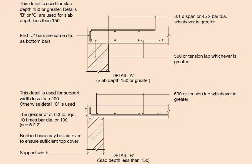
For external unrestrained support (for example, slabs supported by masonry walls), the bottom reinforcement should be returned by 0.1 x span. Where partial fixity exists (for example, end support of a slab supported by beams), the bottom reinforcement should be returned by 0.15 x span.
At cantilevers, the main top reinforcements should extend into the span by at least 1.5 x times the length of the cantilever or 0.3 times the length of the span whichever is greater. It is also recommended to provide at least 50% of the top reinforcement at the bottom in order to help control deflection.
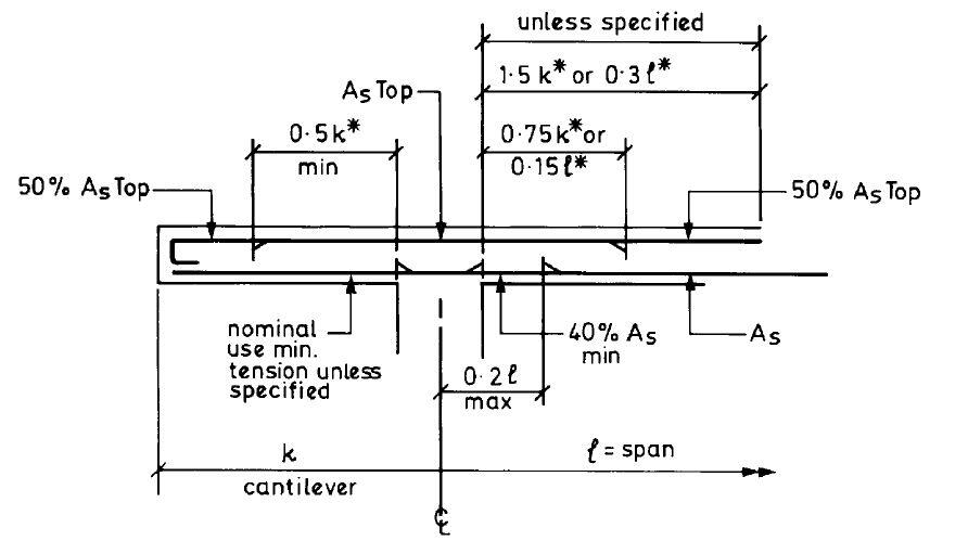
In other circumstances, the curtailment of the main longitudinal reinforcement should be related to the bending moment/shear force diagrams.
Notation for Locating Layers of Reinforcement
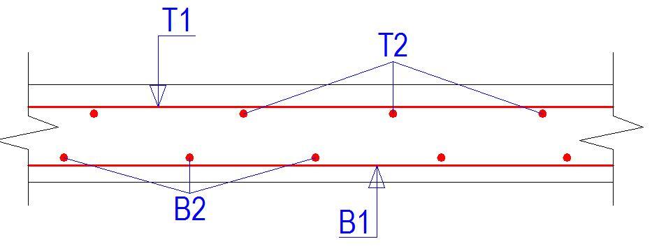
Reinforcement is fixed in layers starting from the bottom of the slab upwards and bar marks should preferably follow a similar sequence of numbering.
Notation is as follows:
• abbreviation for top outer layer T1 (or TT)
• abbreviation for top second layer T2 (or NT)
• abbreviation for bottom second layer B2 (or NB)
• abbreviation for bottom outer layer B1 (or BB)
Reinforcement Bars and Indicator Lines
In slab detailing, every reinforcement bar is assigned a bar mark. Each bar mark is unique to a type of reinforcement, grade, size, dimensions, and shape. Therefore a bar mark can represent a single bar or a group of bars. Every bar mark is represented on plan by a typical bar drawn to scale, using a thick line (generally, rebar lines should be thicker than all other lines in the detailing drawing).
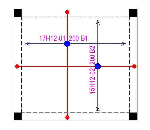
The reinforcement bar is positioned approximately midway along its indicator line (also called the call-out line), the junction of the bar and the indicator line is highlighted by a large dot. The first and last bars in a zone of several bars are represented by short thick lines, their extent indicated by arrowheads. Bends or hooks, when they occur at either end of the typical bar are represented by a medium dot or similar as shown in Figure 7(b).
Sometimes, hooks or bent bars are drawn on plan as though laid flat (see Figure 7a). This is actually the commonest method of detailing. However, confusion on site can result if some of these bars are required to be fixed flat and some upright. Sections and notes should be provided to clarify this method if used.
Example
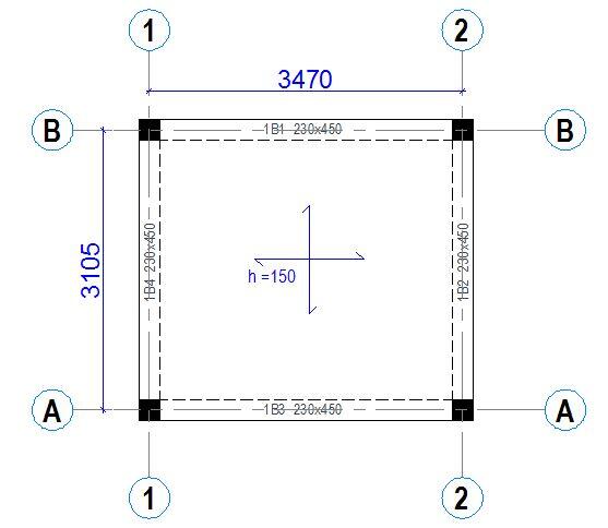
Let us consider the slab panel shown above with simply supported assumptions. The reinforcement specified in all directions is H12 @ 200mm spacing.
To calculate the number of rebars to be provided in each direction, the following steps can be followed;
In the short span direction;
n = [(lx – bw – p)/p] + 1 = [(3105 – 230 – 200)/200] + 1 = 14.375 (provide 15 Nos of H12 bars)
Note: p is the spacing of the bars and it is assumed that the laying of slab mat reinforcement starts at 0.5p from the face of the beam.
Similarly in the long span direction;
n = [(ly – bw – p)/p] + 1 = [(3470 – 230 – 200)/200] + 1 = 16.2 (provide 17 Nos of H12 bars)
Note: On site, you will eventually have a spacing that is slightly less than 200 mm center to centre (about 178 mm, which is good/conservative). But if you provide 16 numbers, you will have spacing greater than 200 c/c which is not too good.
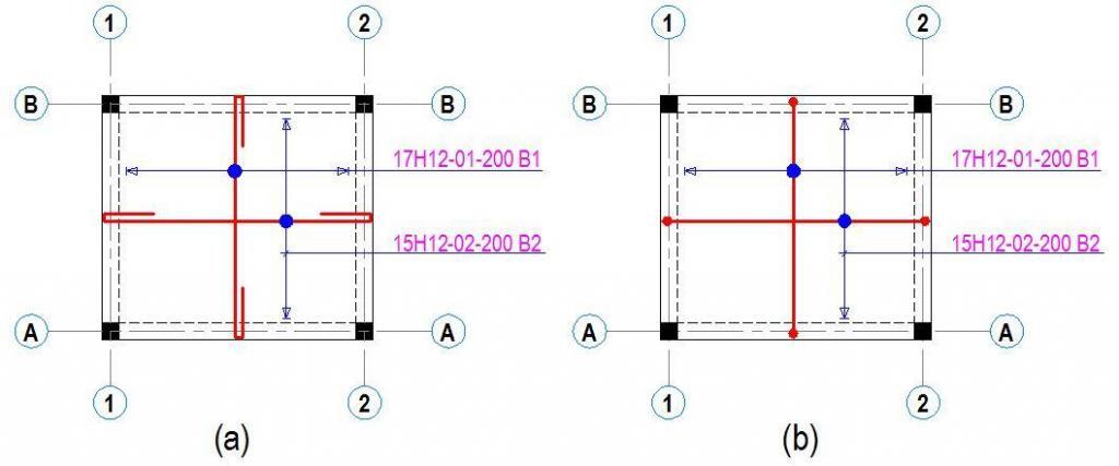
In figure 7(a) the bend/hook is drawn in plan as flat, while in figure 7(b) it is represented using a medium dot. Either method is acceptable in standard, but in Nigeria, the former is more popular.
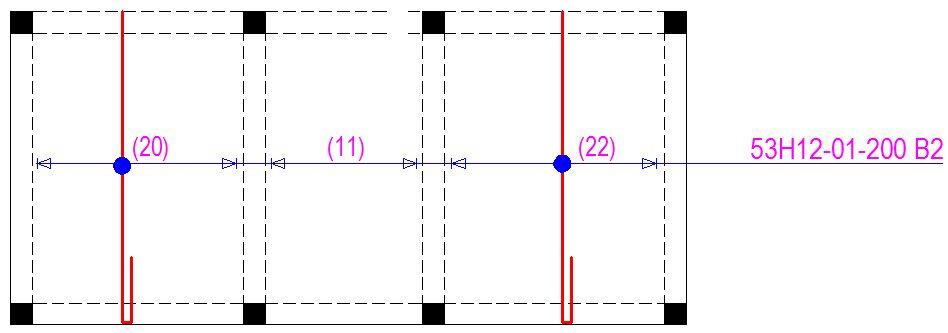
When there are multiple zones/panels with similar bar marks, the number of bars in each panel can be written and the total summed up in the call out. This saves time and paper space in the detailing of reinforced concrete slabs. An example is shown in Figure 8;
When there are serious space restrictions on the paper, the calling up of bars can be written along the indicator lines as shown in Figure 9. In extreme cases, it can be written along the bars.
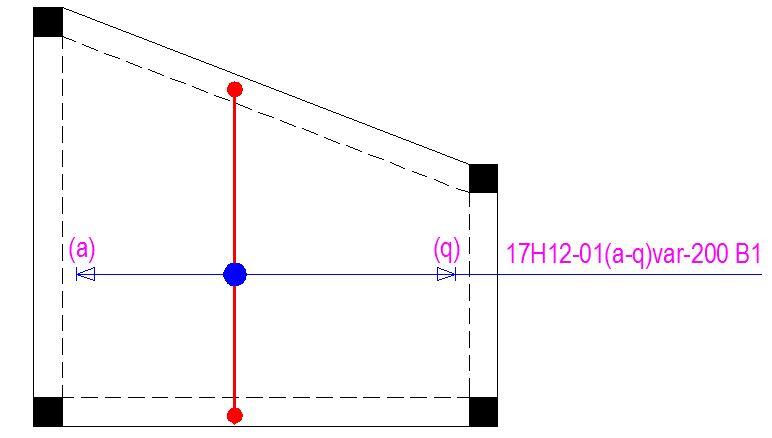
When bars are to be detailed in a panel/zone that is varying in dimension, the approach shown in Figure 10 should be used;
Edge reinforcement
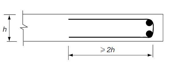
According to Clauses 9.3.1.4 of EC2, reinforcement should be placed along free (unsupported) edges of slabs and at corners that are supported on both sides. This allows the distribution of local loads which helps to prevent unacceptable cracking. This reinforcement may be supplied in the form of U-bars as shown in Figure 11.




Very Useful, Thank You
THIS IS POWERFUL. THANKS
I learn most important things .and thanks
Very helpful.
Thanks and God bless you, sir.
Simple and apt .
This is impressive
Thank you for this
When calculating the number of bars on one slab panel, can we subtract the concrete cover from both ends
Thay is, n= Span length -2(concrete cover)/spacing +1
Is it right to do this?
nice
Hi would you please explain more about the layering of bars for countless times there is clash/conflict re which bars are TT/T1 and which bars are T2 in conflicting zone. Example along the 4 edges of a solid slab with discontinuous edges at corners the T1 bars along the short direction meet the T1 bars along the long directions near the corner. Also there are time due to those clashes and other practical reason, it is better to have B1 or T1 bars along the longer span instead of the default shorter span.