A structural engineer posted a picture of a large cantilever slab construction on LinkedIn, and so many reactions have followed the picture due to its size and dimensions. Cantilever structures are generally structures that are fixed (or continuous) at one end, and free (unsupported at the other end). As a matter of fact, they are one of the most challenging structures to design given that the bending moment increases with the square of the length, while the deflection increases to the fourth power of the length. As a result, controlling deflection and dealing with stability of large span cantilever structural systems is always a challenge in design.
Read Also…
Design of large span cantilever structures
Structural design of cantilever slabs
We have posted the comments from various professionals on the post to enable us review, scrutinize, and assess the possibility of designing and constructing such type of structure. However the exact span, design data, calculation sheet, and drawings of the structure were not made available, but a lot of people still managed to lend their voices to the construction.
Let us look at their responses below;
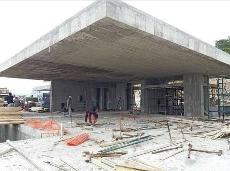
(1) A senior engineer from New Delhi area of India doubted the stability of the structure citing inadequate support conditions. He suggested that cables could have been used to support the slab further. According to him,
Doesn’t look like it is safe. The slab is too thick whereas the supporting structures are too thin. Also, normally such thick slabs are designed as flat slabs but I don’t see the flat slab connection type being followed at the support junctions. It looks like to take care of the cantilever load and moments coming on the slab the thickness has been increased. Hopefully the designer has checked all the loads and moments properly otherwise it is going to fail in the long run. The best option would have been to provide some sort of pulling arrangements at the top corner of the slab via cables or pin jointed stereo frames at the outmost corner where there is no support from the bottom of the slab and that way the designer would have succeeded in decreasing the slab thickness as well as given an aesthetic look to it.
(2) Another structural engineer from India attributed it to the power of post tensioned concrete design as he wrote;
Power of PT Design
(3) A registered Professional Engineer (P.E) from the USA commented that the loading on the slab may not be high enough to cause serious problems. According to him,
There are some issues, but if the math and science can be proved it can be done. Usually in situations like this, the loading is majorly under developed so when you compare the loading to the strength, it will be sufficient. But in reality the loading is not high enough. Expect 250 psf live load to 500 psf live load and use a heavy concrete weight with 2000 pci strength or 1500 pci strength. They tend to screw up the mix design on these.
(4) A retired engineer from India wrote;
This is possible. The slab must have been designed as two adjecent edges supported slab. I did come across such a design in early stages of my career as structural engineer
(5) A registered civil engineer from Nigeria expressed doubts over the safety of the slab and said,
The span of this cantilever slab seems to be much, and may be unsafe.
(6) A senior structural engineer (M.Tech) from India also considered the safety of the structure to be doubtful due to the lack of a back span and said,
That seems to be a dangerous cantilever. I don’t see a continuous backing portion either. I hope it must have been designed and checked well.
(7) The idea of lack of back-span was also raised by another engineer who said that it does not matter whether the slab was post tensioned or not. According to him;
No back span, seems to be very dangerous. Whether it is PT or NonPT the cantilever behaviour is same. Looks very huge self weight due to higher thickness
(8) A civil engineer from Nigeria pointed out that a blend of lightweight materials on a steel framing can be used to achieve the structural system. According to him,
It depends on the material used to achieve the cantilever. POP or any lightweight material can be used to achieve this cantilever then the frame can be metal. The rest will be a good aesthetic work to produce a good look. No load should be on the artificial slab.
However, materials like POP may not be adequate or durable given the exposure of the structure. However, the use of polystyrene can work, after which it will be screeded with mortar to give a finished appearance of concrete. Polystyrene has be extensively used for doing concrete fascia and other building elements.
(9) Another Engineer pointed out that the image could be edited, because the support system provided for the structure (walls and columns from the picture) looked too small to support the massive weight of the cantilever structure. According to him,
Looks to me like a edited image of the structure but if it’s true I don’t know how this structure is safe. Supports looks weaker than the heavy cantilever slab resting on it.
(10) Another engineer who is rounding up his PhD in Spain pointed out that the structure must be post tensioned, however, it seems unsafe especially in the presence of any seismic event. According to him;
Post-tension! But even if it’s not behaving similarly in cantilever spans. The thickness! Huge Self weight! with moderate seismic load or any lateral load, it will make severe damages! Please, treat Infrastructure in high responsibilities.
(11) An independent Structural Engineer with over 39 years of experience from India suggested that the most important thing is to balance the weight of the structure and the moment generated at the supports. According to him,
Main thing is to see the balancing weight and Moment at the support and the section of slab should be with max. thickness at supports and minimum thickness at free end , we have already designed and constructed a stadium at Dehradun in 2001 & standing safe till date.
However, in as much as the exact details of the structure are not available, what do you think?

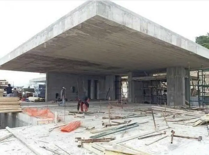






I think d materials used for framing the system are not concrete but steel. Because supports are small and no continuous span to support the cantiliver.
to me it is an edited photo- a cantilever of that magnitude will collapse over time since it has no any counterweight. However, without calculations or measurements one cannot make a conclusive statement on this matte
I think by just looking at the picture on one angle and without structural drawings is not sufficient to determine if the structure is safe or stable due to the large cantilever. Again base on the picture, it seems that there is a facade on the north side of the structure and another cantilever roof on the northwest of the the structure. I don’t know if the designer used this facade as a counterweight and the adjacent cantilever is attached to the structure to keep the structure or structures in equilibrium. As mentioned on the last sentence of the article controlling deflection and dealing with stability of large span cantilever structural systems is always a challenge in design. The slab with long cantilever can be done if analyzed and designed properly and satisfying the building code requirements.
It is possible considering the one triangle having two adjacent sides supported will give support to the outer at the ends of supports defining a common base for the two triangles.
Common design seems to be enough in strength design of flexural bending, one-way two-way shear, deflection check and stability of overall structure.
lmportant point is the connecting system between the large slab and footing.
Connecting system, according to photo, is walls and pier. Wall looks thin. The stresses and strain may too large at the junction of wall and slab. This situation must be searched throughly both amount and direction of stresses. And then special detailing must be provided accordingly. Otherwise long-term durability will be problem. Concrete cover may peel off due to high strain and warping stress (due to Mxy Vxy).
Common design seems to be enough in strength design of flexural bending, oneway twoway shear, deflection check and stability of overall structure.
lmportant point is the connecting system between large slab and footing.
Connecting system according to photo is walls and pier. Wall looks thin. The stresses and strain may too large at the junction of wall and slab. This situation must be searched throughly both amount and direction of stresses. And then special detailing must be provided accordingly. Otherwise long-term durability will be problem. Concrete cover may peel off due to high strain and warping stress (due to Mxy Vxy).
Reinforcing curtains inside the wall must be linked enough each others. Otherwise vertical wall reinforcing bars may bent out and wall may burst open.
It seems to be feasible… I’ve drawn the FBD in my mind and it’s looking good.
I feel the internal cantilever slab structure can be a web design covered by a thin dummy finish material. The web design has help to distribute load equally on the section causing no harm.
In my opinion, it is a steel frame structure with rigid end connections with columns and beams. Once steel structure has been build and it’s stability checked, then the walls and columns are concealed with normal high strength concrete. Roof steel is concealed with light weight concrete. One reason to conceal steel could be the structure built in coastal area where steel could get corroded in short span of time. There will be slope on the top for the drainage purpose. The fascia is made uniform for architectural purpose and it’s thickness could be maximum 3 inches.
The slab seems 40 to 48 inch thick and if the engineer tried to make such a thick slab using tons of steel and concrete, then what he tried to achieve, except risk of lives.
The cantilever and overturning forces are probably balanced by the floor structure below, in that the tensile forces on teh end of hte supporting walls are suitably anchored to an equivalent mass.
The slab itself can be thought of as roughly two triangles with one triangle over the supports holding the other triangle, with a yield line between the two triangles drawn from corner to corner.
Thought this. This is possible since then, the structure could be resting on both sides and cantilevered from the triangle edge. The cantilevere beyond the first triangle, could be just dummny , unless the whole angle of projection is a zoomed picture.
Well, without a proper view of the structure its pretty hard to state the strucrural framing enlisted. I witnessed the construction of somwthing similar in Lagos, (Banana island). At first glance it appeared to be a free standing cantilever slab, but a closer inspection showed that it had some massive upstand beams supporting the slab which could only be viewed from above.
Thank you for this article
The seismic/dynamic response certainly won’t look good. Maybe it has post-tensioning. Nonetheless could be made lighter with composites, at least 35%.