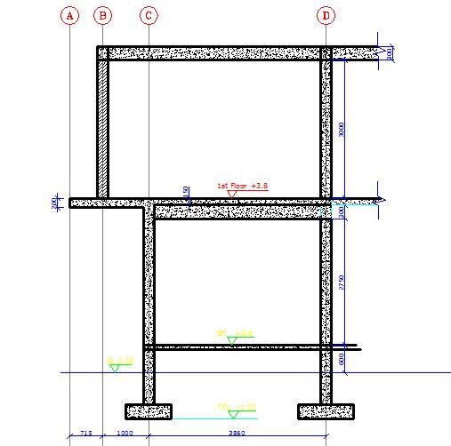
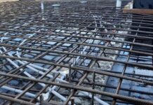
Cantilever slabs are common features in residential and commercial buildings due to the need to have bigger spaces on upper floors. To achieve this, architects normally extend the slab beyond the ground floor building line, thereby forming a cantilever. Cantilever slabs in reinforced concrete buildings are usually characterised by a reinforced concrete slab projecting from the face of the wall and having a back span that extends into the interior panels of the building.
The design of reinforced concrete cantilever slab is usually governed by serviceability limit state requirements. Typically, the design involves the provision of adequate concrete thickness and reinforcement to prevent excessive deflection and vibration.
During the detailing of reinforced concrete cantilever slabs, the main reinforcements are provided at the top and they extend into the back span by at least 1.5 times the length of the cantilever or 0.3 times the length of the back span, whichever is greater. Furthermore, it is important to provide at least 50% of the reinforcement provided at the top, and at the bottom.
In this article, we are going to show how we can analyse and design cantilever slabs subjected to floor load and block wall load according to the requirements of EN 1992-1-1:2004 (Eurocode 2).

Worked Example – Design of Cantilever Slabs
A cantilever slab 200 mm thick is 1.715m long, and it is supporting a blockwork load at 1.0m from the fixed end. Design the slab using the data given below;
Purpose of building – Residential
fck = 25 Mpa
fyk = 460 Mpa
Concrete cover = 25 mm
Height of block wall = 2.75 m
Unit weight of concrete = 25 kN/m3
Unit weight of block with renderings = 3.75 kN/m2
Load Analysis
Self weight of slab = (25 × 0.2) = 5 kN/m2
Finishes (assume) = 1.2 kN/m2
Partition allowance = 1.0 kN/m2
Total characteristic permanent action (pressure load) gk = 7.2 kN/m2
Permanent action from wall Gk = 3.75 × 2.75 = 10.3125 kN/m
Variable action on slab qk = 1.5 kN/m2
At ultimate limit state;
n = 1.35gk + 1.5qk
n = 1.35(7.2) + 1.5(1.5) = 11.97 kN/m2
Ultimate load from wall = 1.35 x 10.3125 = 13.92 kN/m
Design Forces
MEd = (13.92 × 1) + (11.97 × 1.7152)/2 = 31.523 kNm
VEd = (13.92) + (11.97 × 1.715) = 34.45 kN
Flexural design
MEd = 31.523 kNm
Effective depth (d) = h – Cnom – ϕ/2 – ϕlinks
Assuming ϕ12 mm bars will be employed for the main bars
d = 200 – 25 – 6 = 169 mm
k = MEd/(fckbd2) = (31.523 × 10⁶)/(25 × 1000 × 1692) = 0.044
Since k < 0.167, no compression reinforcement required
z = d[0.5+ √(0.25 – 0.882K) ]
z = d[0.5+ √(0.25 – 0.882(0.044))] = 0.95d
As1 = MEd/(0.87fyk z) = (31.523 × 10⁶)/(0.87 × 460 × 0.95 × 169) = 490 mm2/m
Provide X12@200 c/c TOP (ASprov = 565 mm2/m)
Check for deflection
ρ = As,prov /bd = 565 / (1000 × 169) = 0.0033
ρ0 = reference reinforcement ratio = 10-3√(fck) = 10-3√(25) = 0.005
Since if ρ ≤ ρ0;
L/d = K [11 + 1.5√(fck) ρ0/ρ + 3.2√(fck) (ρ0 / ρ – 1)(3⁄2)
k = 0.4 (Cantilevers)
L/d = 0.4 [11 + 1.5√(25) × (0.005/0.0033) + 3.2√(25) × [(0.005 / 0.0033) – 1](3⁄2)
L/d = 0.4[11 + 11.363 + 5.9159] = 11.311
βs = (500 Asprov)/(fyk Asreq) = (500 × 565) / (460 × 490) = 1.253
Therefore limiting L/d = 1.253 × 11.311 = 14.172
Actual L/d = 1715/169 = 10.147
Since Actual L/d (10.147) < Limiting L/d (14.172), deflection is satisfactory.
Exercise for Students
(1) Provide distribution bars
(2) Verify the section for shear
(3) Check for cracking
(4) Do the detailing sketches
Thank you for visiting Structville today, and God bless.


why unit weight of concrete = 25kN/m3?
It's obvious you're not familiar with RC design to Eurocodes (BS EN 1991-1-1:2002). The bulk density of normal weight concrete(24kN/m³) which you know from BScodes was increased to account for embedded reinforcements and it's stated as 25kN/m³ for 'reinforced normal weight concrete'.
I’m very happy with this fact.This goes to show that you’re used to BS & BS EN.But truth be told,in this country,24N/m^3 will still be my choice because of QC issue.
It`s prette much the same as we calculate in Ukraine.
Helpful. Thanks
Thanks for the information very useful and informative.
Thanks our Engineer. God bless you
thank you
Thank you so much this example is really helpful
You are highly welcome
YOUR EXAMPLE IS BRIEF AND TO THE POIN
KEEP IT UP
VERY HELPFULL
VERY HELPFULL
What about the half weight of the beam acting on the wall
What is the right depth of 4 ft concrete cantilever
Design a cantilever slab of 1.5m span to carry a super imposed load 2KN/m2 using M20 grade concrete and fe 415 grade steel?
thonk you for teaching me!
What of the slabs that are surrounded by 3 beams and one side is free but having a wall in top of it
This was very helpfull, thank you
Good practical illustration with practical example of buildings. this certainly helps graduates to bridge gap between theory and practice. However, a floor plan could have assisted in us assessing the load path.
The roof slab indicated on drawing there is transferring load to the wall which in turn transfer load to cantilever slab supporting the wall. Even though it was for concept illustration, load path needs to be correctly established, otherwise building collapse tikamama!!!