Formwork is an important aspect of the construction of reinforced concrete construction. Column formwork design and construction have evolved over the years with so many alternatives in terms of material selection and installation procedures. Reinforced concrete columns are vertical compression members whose depth to thickness ratio is less than 4, otherwise, it should be described as a shear wall. ACI 318 defined a column as a member with a ratio of height-to-least-lateral-dimension exceeding 3 and is used primarily to support axial compressive load.
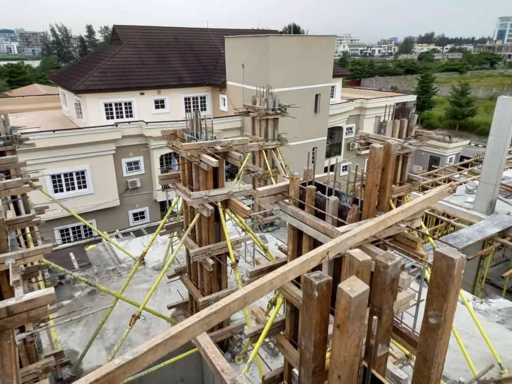
Traditionally, column formworks are entirely constructed from timber planks or plywood with studs, wales, and struts for support. In this case, the timber planks must be sawn to the size of the column with a proper allowance for edge laps and/or closure. The planks are usually joined together through nailing. If the columns in the building are not of the same dimensions, reuse of the column formworks becomes difficult if not impossible. Furthermore, during dismantling, the formworks are prone to damage.
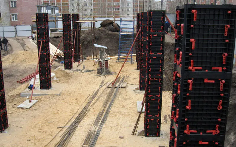
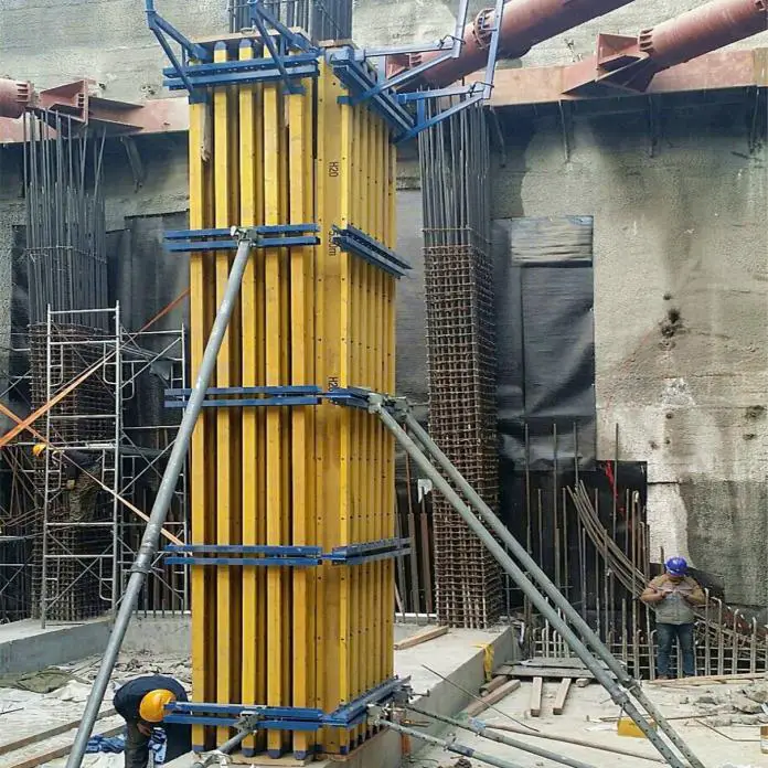
The modern column formwork systems available right now are modular in nature and allow quick assembly and erection on-site while minimising labour and crane time. They are available in steel, timber panels, plastic, aluminium, and even cardboard (not reusable but recycled) and have a variety of internal face surfaces depending on the concrete finish required. Innovations have led to adjustable, reusable column forms which can be clamped on-site to give different column sizes.
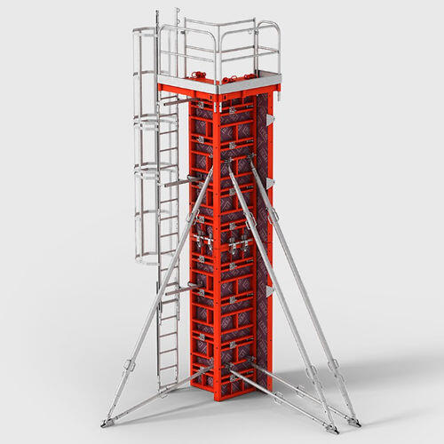
A composite system consisting of wooden panels and steel framing is available and offers the advantage of being lightweight when compared to formwork systems that are made of steel. In constructions works where cranes are not available, steel column formworks have been found to be unattractive because of weight. However, modern modular plastic formworks are available which offer lightweight, flexible, and very good re-use potentials to contractors.
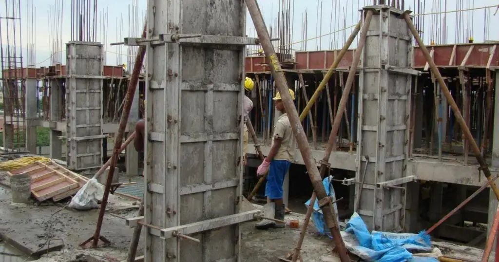
Column formworks can also be constructed locally using 20 mm thick plywood, timber studs (or H-beams/Joists), and clamps. Different types of clamps are available and can be constructed locally by welding threaded rods to Y16mm reinforcement bars as shown in the Figure below. Off-cuts of Y25mm bars or strong timber members can be used to hold the column panels and clamps in place. The advantage of this system is the fairly high level of re-use, but the setup and clamping process is more tedious when compared with other types of modular formworks.
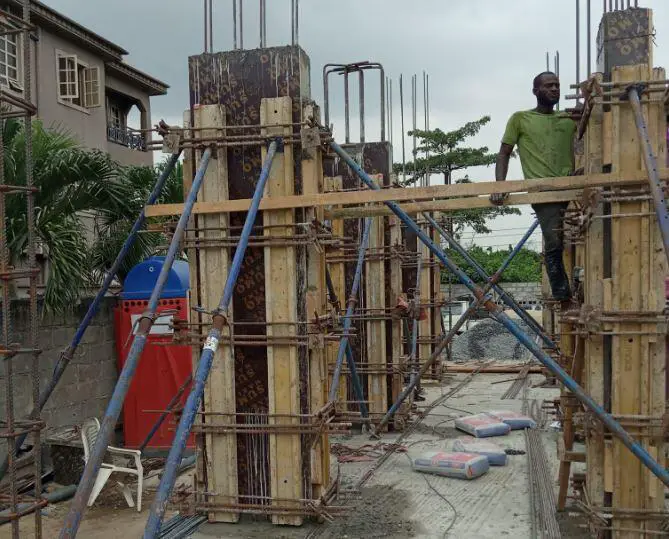
Construction Sequence of Column Formworks
The basic construction sequence using the modular type of column formwork is as follows:
- The column setting out is done as appropriate and the rebars installed.
- The concrete kicker of about 75mm thick is cast in the appropriate location
- The column forms are assembled and positioned to enclose the column reinforcement.
- The column formworks are then positively restrained and braced using props.
- Proper checks are done to ensure that columns are perfectly straight and well-aligned before concreting commences.
- Concreting is done with minimum disruption of the formwork position.
- Column formwork is checked for verticality and alignment after the concreting
- Once the concrete has hardened sufficiently the formwork is stripped and moved to the next position manually or by crane. Disposable forms may be left in place for an extended period to aid curing and strength gain of the concrete before removal.
Other Considerations in Column Formwork Installation
- The column forms are designed for specific maximum concrete pressures. The concrete placement rates have to be adjusted to keep the concrete pressure within the specified limits.
- The assembled formwork has to be restrained at the base properly to avoid displacement, and grout loss during concreting.
- In some metal systems, the push/pull props used to stabilise the column formwork are integral.
- Some systems can be moved on wheels rather than by crane.
- The formwork and access equipment can be moved in a single operation with some systems
- Some metal systems can be easily adjusted in plan size and height (by stacking additional panels on top of each other).
Lateral Pressure on Column Formworks
One of the most important parameters in the design of vertical formworks is the lateral pressure exerted on the face of the formwork by the fresh concrete. The lower the plastic viscosity and yield stress of the fresh concrete the more the original lateral pressure will be. However, faster rates of hardening will lead to faster rates of decay in the lateral pressure. Lateral pressure occurs only as long as the concrete is in a fresh state.
The magnitude of pressure exerted by fresh concrete depends on the following;
- The depth of fresh concrete from the top (free surface) to the depth under consideration.
- The unit weight of the concrete (ρc)
- The rate of concrete placement (R)
- Temperature of concrete during placement (T)
- Unit weight coefficient (Cρ) which depends on the unit weight of the concrete
- Chemistry coefficient (Cc) which depends on the type of cementitious materials
- Method of concrete placement
According to the ACI Committee 347, the formula for calculating the maximum lateral pressure exerted by fresh concrete on vertical column formworks is;
Pmax = CρCc[7.2 + 785R/(T + 17.8)]
The unit weight coefficient Cρ can be calculated using the Table below;
| Density of concrete | Unit weight coefficient (Cρ ) |
| Less than 2240 kg/m3 | Cρ = 0.5[1 + ρc/2320] but not less than 0.8 |
| 2240 – 2400 kg/m3 | Cρ = 1.0 |
| More than 2400 kg/m3 | Cρ = ρc /2320 |
The value of the chemistry coefficient Cc can be picked from the Table below;
| Type of cement | Chemistry Coefficient Cc |
| Types I, II, and III without retarders | 1.0 |
| Types I, II, and III with retarders | 1.2 |
| Other types or blends containing less than 70% slag or 40% fly ash without retarders | 1.2 |
| Other types or blends containing less than 70% slag or 40% fly ash with retarders | 1.4 |
| Other types or blends containing more than 70% slag or 40% fly ash | 1.4 |
In the UK, the formula for calculating the pressure on formworks according to CIRIA Report 108 is given by the equation below, which must not be greater than the hydrostatic pressure.
Pmax = [C1√R + C2K √(H1 – C1√R)]γ
Where:
Pmax = Maximum lateral pressure against formwork (kPa)
R = Rate of placement (m/h)
C1 = Coefficient for the size and shape of the formwork (1 for walls).
C2 = Coefficient for the constituent materials of the concrete (0.3 – 0.6).
γ = Specific weight of concrete (kN/m3).
H1 = Vertical form height (m).
K = Temperature coefficient K = (36/T + 16)2
Steps in the Design of Column Formwork
The following steps can be adopted in the designing of column formworks;
- Determine all the necessary design parameters such as the dimensions of the column, type of concrete, rate of placement, and temperature of placement.
- Calculate the design lateral pressure from the fresh concrete, and draw the lateral pressure distribution diagram.
- Select suitable plywood (with known mechanical properties) for the sheathing
- Select a trial timber backing section (with known mechanical properties) and assume a trial spacing
- Determine the bending moment, shear, and deflection of the plywood using the design pressure distribution diagram.
- Determine the bending moment and shear on the backing timbers and compare it with the permissible stress of the section.
- Design the steel/timber yokes and tie rods by checking the stresses on them. Compare this with the allowable stresses on the members.






Nice information! I should add that the column can be built with aluminium formwork.
I have a quick question before my 2-storey duplex foundation is cast. They are pad foundations with 29 columns (225mmx225mm cross sections and 1500mm height) sitting on 29 footings (1m x 1m x 0.3m).
My site engineer wants the foundation block wall that should connect these columns to serve as formwork for casting the columns. Is this advisable? He wants to put the column reinforcement in the excavation, align them, lay the foundation block walls to almost touch the column reinforcements, use two pieces of wooden planks as formwork on the two adjacent sides of the columns, and pour concrete in the square shape formed by the blocks and plants.
I am worried that since the block can’t removed after casting, the columns will not set properly and achieve their maximum strength. Any suggestions from someone’s experience?
The content is technical but well-explained, making it suitable for professionals and students in the field. The inclusion of step-by-step procedures and illustrative diagrams adds significant value to the post. It’s a valuable resource for those seeking in-depth knowledge about column formwork.