Shear walls are structural members that provide additional lateral stiffness to a building by resisting shear, moment, and axial forces, which are produced due to gravity and lateral loads. In some design cases, the entire lateral loads coming to a building assumed to be resisted by shear walls alone, especially when it is the major stabilising/bracing component of the building. The design of shear walls involves providing adequate cross-section and reinforcements to resist bending, shear, axial, and twisting forces due to gravity and lateral loads.
For an element to be described as a reinforced concrete wall, the length to thickness ratio should be equal to or greater than 4 (Clause 9.6.1, Eurocode 2). A shear wall is said to be short when the height-to-width ratio is less than or equal to one, while it is said to be slender when the height-to-width ratio is greater than or equal to four. For slender walls, bending deformation is dominant, while in short walls, shear deformation is dominant. When the height-to-width ratio is in-between one and four, then the shear wall undergoes both shear and bending deformations.
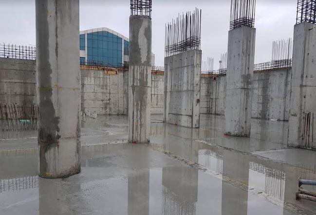
Forces Acting on Shear Walls
Shear walls are designed to resist bending moment, shear, axial, and uplift forces, especially when they are subjected to lateral actions. The lateral forces acting in the plane of a shear wall attempts to lift up one end of the wall and push the other end down. Uplift forces are greater on tall walls and less on low walls. Shear walls resist the shear force parallel to the plane of the wall by cantilever action.
Axial forces in a Shear wall
The axial load in a wall may be calculated assuming the beams and slabs transmitting the loads to it are simply supported.
Transverse moments
For continuous construction, transverse moments can be calculated using elastic analysis. The eccentricity is not to be less than h/30 or 20 mm where h is the wall thickness.
In-plane moments
Moments in the plane of a single shear wall can be calculated from statics. When several walls resist forces, the proportion allocated to each wall should be in proportion to its stiffness.
Location/Placement of Shear of Shear Walls
In a tall building where the shear wall is used for lateral stability, it should be located on each level of the structure. Preferably, shear walls of equal length should be placed symmetrically on all four exterior walls of the building to form an effective box structure. When the shear walls in the exterior frame could not provide sufficient strength and stiffness, the shear walls should be added to the interior frame as well.
If the shear wall is placed at the interior frame of a building, it attracts and resists higher internal forces but may not be too effective in reducing the maximum lateral deflection of the building. However, if a shear wall is placed at the ends of a building, the lateral deflection is reduced considerably when compared to the later.
Architectural disposition in a building may not always give the room for optimum placement of shear walls for good structural performance. In some areas such as lift areas or window/door openings, coupled shear walls may have to be used. However, the best position or arrangement of shear walls in a building is a symmetrical arrangement whereby the shear centre (centre of rotation) will coincide with the centre of gravity of the building in order to reduce or eliminate torsion (twisting) due to lateral loads.
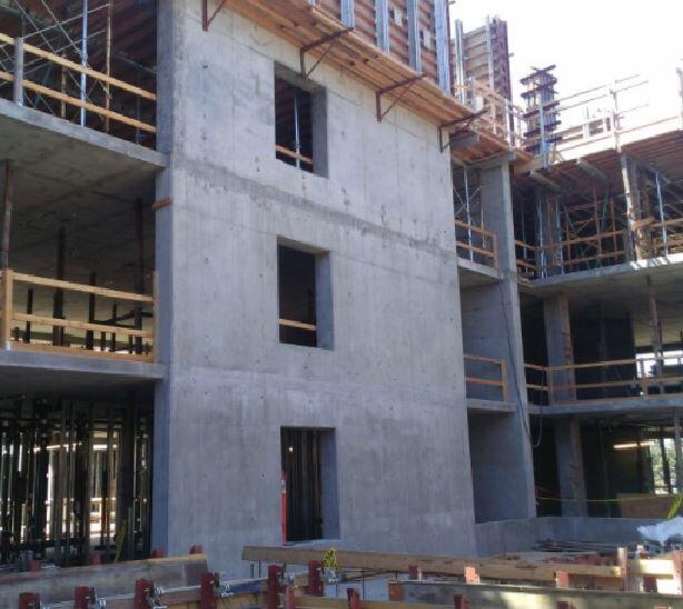
Functions of Shear Walls
- Shear walls must provide the necessary lateral strength to resist horizontal wind and earthquake forces.
- They provide resistance against sliding through connections.
- They also provide lateral stiffness to prevent the roof or floor above from excessive side sway.
- When the shear walls are stiff enough, they prevent floor and roof framing members from moving off their supports.
- Buildings that are sufficiently stiff usually suffer less structural damage due to the presence of shear walls.
Structural Action of a Shear Wall
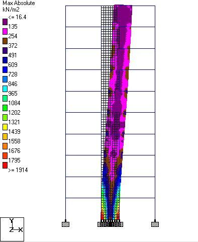
In a shear wall, the primary mode of deformation is mainly due to flexure but not shear. The mode of deformation of shear walls is such that it has maximum slope at the top and least at the bottom which is the flexural mode shape. The structural action of a shear wall resembles that of a cantilever beam.
Structural Design of Shear Walls
The amount of reinforcement needed for proper detailing of a reinforced concrete wall may be derived using strut-and-tie model. If a wall is however subjected predominantly to out-of-plane bending, the design rules and guidelines for slabs apply. In Eurocode 2, the requirements for the design of columns and shear walls are not so different except in the following areas;
■ The requirements for fire resistance
■ Bending will be critical about the weak axis
■ Rules for spacing and quantity of reinforcement
Reinforcement Detailing of Shear Walls
(a) Minimum and maximum area of vertical reinforcement
According to clause 9.6.2 of Eurocode 2, the minimum and maximum amounts of reinforcement required for a reinforced concrete wall are 0.002Ac and 0.04Ac outside lap locations respectively. It is further stated that where minimum reinforcement controls design, half of this area should be located on each face. The distance between two adjacent vertical bars should not exceed three times the wall thickness or 400 mm, whichever is lesser.
(b) Area of horizontal reinforcement
According to clause 9.6.3 of Eurocode 2, horizontal reinforcement should be provided at each face and should have a minimum area of 25% of the vertical reinforcement or 0.001Ac, whichever is greater. The spacing between two adjacent horizontal bars should not be greater than 400 mm.
(c) Provision of links
If the compression reinforcement in the wall exceeds 0.02Ac, links must be provided through the wall thickness in accordance with the rules for columns in clause 9.5.3 which are:
The diameter of the transverse reinforcement should not be less than 6 mm or one-quarter of the diameter of the largest longitudinal bar whichever is greater. The maximum spacing is to be Scl, max
Scl, max is the minimum of;
- 20 times the diameter of the smallest longitudinal bar
- The lesser dimension of the wall i.e. the thickness
- 400 mm
The maximum spacing should be reduced by a factor of 0.6 in the following cases;
- In sections within a distance equal to 4 × thickness of wall above or below a beam or slab.
- Near lapped joints, if the diameter of the longitudinal bar is greater than 14 mm. A minimum of three bars evenly placed in the lap length is required.
Where the main reinforcement (i.e., vertical bars) is placed nearest to the wall faces, transverse reinforcement should be provided in the form of links with 4 per m2 of the wall area.
Design Example of Shear Walls
Design a 225 mm thick shear wall of 3.6 m height at the ground floor of the building. The shear wall is carrying a 200 mm thick slab on the first floor of the building. The action effects on the shear wall are as follows;
Vertical loads
Dead Load Gk = 300 kN/m
Live load Qk = 55 kN/m
Vertical load due to in-plane bending and wind Wk = ±650 kN/m
Vertical load due to in-plane bending and imperfections GkH = ±60 kN/m
Maximum moment out-of-plane, floor imposed load as leading action M = 40 kN/m @ ULS
Maximum moment out-of-plane, floor imposed load as accompanying action M = 35 kN/m @ ULS
fck = C25/30; fyk = 500 N/mm2
Check slenderness of wall at ground floor
Effective length, l0 = 0.75 × (3600 – 200) = 2550 mm (Table C16)
λ = 3.46 × l0/h = 3.46 × 2550/225 = 39.213 (Cl. 5.8.3.2(1))
Limiting slenderness, λlim = 20 ABC/n0.5 (Cl. 5.8.3.1(1))
where;
A = 0.7
B = 1.1
C = 1.7 – rm
where;
rm = M01/M02 = say = –0.25
C = 1.7 – (-0.25) = 1.95
n = NEd/Acfd
where;
NEd (assuming wind is the leading variable action) = 1.35Gk + 1.5Qk1 + 1.5Ψ0Qki
= 1.35(300 + 60) + 1.5(650) + (1.5 × 0.7 × 55) = 486 + 975 + 57.75 = 1518.75 kN/m
Acfd = (225 × 1000) × (0.85 × 30/1.5) = 3825 kN
Therefore, n = 1518.75/3825 = 0.397
λlim = 20 ×( 0.7 × 1.1 × 1.95)/0.3970.5 = 47.66
Therefore as λ < λlim wall is not slender and therefore no secondary moments.
Combinations of actions
(a) At ULS, for maximum axial load, Wk is leading variable action
NEd = 1.35Gk + 1.5Qk1 + 1.5Ψ0Qki
= 1.35(300 + 60) + 1.5(650) + (1.5 × 0.7 × 55) = 486 + 975 + 57.75 = 1518.75 kN/m
MEd = M + eiNEd ≥ e0NEd (Cl. 5.8.8.2(1), 6.1.4)
where
M = moment from 1st order analysis = 35 kNm/m
ei = l0/400 = 2550/400 = 6.375 mm (Cl. 5.2(7), 5.2(9))
e0 = h/30 ≥ 20 mm = 20 mm (Cl. 6.1.4)
MEd = 35 + (0.006375 × 1518.75) ≥ 0.020 × 1518.75
MEd = 35 + 9.68 ≥ 30.375 = 44.68 kNm/m
(b) At ULS, for minimum axial load, Wk is leading variable action
NEd = (1.0 × 300) – (1.35 × 60) – (1.5 × 650) + (0 × 55) = –756 kN/m (tension)
MEd = 35 + (0.006375 × 756) ≥ 0.020 × 756
= 35 + 4.82 ≥ 15.12 = 39.82 kNm/m
(c) At ULS, for maximum out of plane bending assuming Qk is leading variable action
NEd = 1.35(300 + 60) + (1.5 × 55) + (1.5 × 0.5 × 650) = 1056 kN/m
MEd = 40 + (0.006375 × 1056) ≥ 0.020 × 1056
MEd = 40 + 6.732 ≥ 21.12 = 46.732 kNm/m
or
NEd = (1.0 × 300) – (1.35 × 60) – (0 × 55) – (1.5 × 0.5 × 650) = -268.5 kN/m (tension)
MEd = 40 + (0.006375 × 268.5) = 41.71 kNm/m
Design load cases
Consolidate (c) into (a) and (b) to consider two load cases:
NEd = 1518.75 kN/m
MEd = 46.732 kNm/m (out of plane)
and
NEd = –756 kN/m (tension)
MEd = 46.732 kNm/m (out of plane)
Design: cover above ground
cnom = cmin + ∆cdev
where;
cmin = max[cmin,b; cmin,dur] (Exp. (4.1))
where
cmin,b = diameter of bar = 20 mm vertical or 10 mm lacers
cmin,dur = for XC1 = 15 mm
∆cdev = 10 mm
cnom = 15 + 10 = 25 mm to lacers (35 mm to vertical bars)
Design using charts
For compressive load:
d2/h = (25 + 10 + 16/2)/225 = 0.19
Interpolate between charts for d2/h = 0.15 and d2/h = 0.2 as shown below
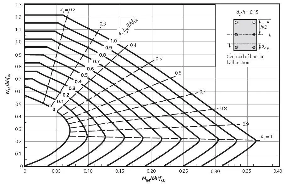
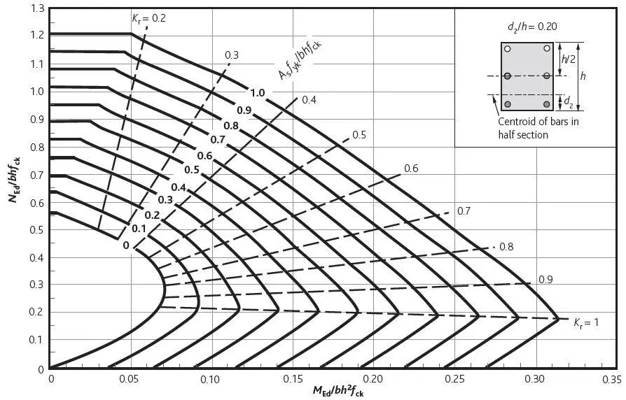
NEd/bhfck = (1518.75 × 103)/(225 × 1000 × 30) = 0.225
MEd/bh2fck = (46.732 × 10⁶)/(2252 × 1000 × 30) = 0.030
Gives:Asfyk/bhfck = 0
Therefore, minimum area of reinforcement required
As,min = 0.002Ac (Cl. 9.6.2 & NA)
As,min = 0.002 × 225 × 1000 = 450 mm2/m
As,min = 450 mm2/m = 225 mm2/m each face
maximum spacing = 400 mm c/c, minimum diameter of rebar = 12 mm diameter
Try H12 @ 300 c/c on each face
For tensile load and moment
Working from first principles, referring to the figure below and ignoring contribution from concrete in tension,
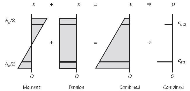
NEd = (σst1 + σst2) × As/2
and MEd = (σst1 – σst2) × As/2 × (d – d2)
So σst1 + σst2 = 2NEd/As
and σst1 – σst2 = 2MEd/[(d – d2)As]
2σst1 = 2NEd/As + 2MEd/[(d – d2)As]
As = (NEd/σst1) + MEd/(d – d2)σst1
σst1 = fyk/γs = 500/1.15 = 434.8
As = (756 × 103/434.8) + (46.732 × 10⁶)/[(182 – 43) × 434.8] = 1738.7 + 773 = 2512 mm2
σst2 = 2NEd/As – σst1 = 601.9 – 434.8 = 167 MPa
By inspection all concrete is in tension zone and may be ignored.
Use 7H16 @ 175 c/c on both sides for at least 1 m each end of wall (Asprov = 2814 mm2).
Horizontal reinforcement
As,hmin = 0.001Ac or 25% As,vert (Cl. 9.6.3(1) & NA)
= 225 mm2 or (0.25 × 2814) = 704 mm2/m
This therefore requires 352 mm2/m each side
Use H10 @ 200 (393 mm2/m) both sides
Links
Check 0.02Ac = 0.02 × 225 × 1000 = 4500 mm2 > 2814 mm2
Therefore, links not required.
.






Intersting
Very good knowledge
For effective length where can I find table C16?
It’s a blessing to have this knowledge