Columns are vertical or inclined compression members used for transferring superstructure load to the foundation. The structural design of reinforced concrete (R.C.) columns involves the provision of adequate compression reinforcement and member size to guaranty the stability of the structure. In typical cases, columns are usually rectangular, square, or circular in shape. Other sections such as elliptical, octagonal, etc are also possible.
Columns are usually classified as short or slender depending on their slenderness ratio, and this in turn influences their mode of failure. In framed structures, columns are either subjected to axial, uniaxial, or biaxial loads depending on their location and/or loading condition. EN 1992-1-1:2004 (Eurocode 2) demands that we include the effects of imperfections in the structural design of columns. The structural design of reinforced concrete columns is covered in section 5.8 of EC2.
When columns are not properly designed, they can fail by;
- crushing
- buckling
- shear, or
- by the combination of any of the above
The steps in the design of reinforced concrete columns are;
- Determine design life
- Assess actions on the column
- Determine which combinations of actions apply
- Assess durability requirements and determine concrete strength
- Check cover requirements for appropriate fire resistance period
- Calculate min. cover for durability, fire, and bond requirements
- Analyse structure to obtain critical moments and axial forces
- Check slenderness
- Determine area of reinforcement required
- Check spacing of bars
Braced and Unbraced Columns
Lateral stability in braced reinforced concrete structures is provided by shear walls, lift shafts, and stairwells. Therefore all lateral actions are transferred and resisted by the stiff stabilising members. In a braced column the axial load and the bending moments at the ends of a column arise from the vertical loads acting on the beams. The horizontal loads do not affect the forces or deformation of the column. The columns do not contribute to the overall horizontal stability of the structure.
In unbraced structures, resistance to lateral forces is provided by bending in the columns and beams in that plane. The column ends can deflect laterally. In a column in an unbraced structure, the axial force and moments in the column are caused not only by the vertical load on the beams but also by the lateral loads acting on the structure and additional moments due to the axial load being eccentric to the deflected column.
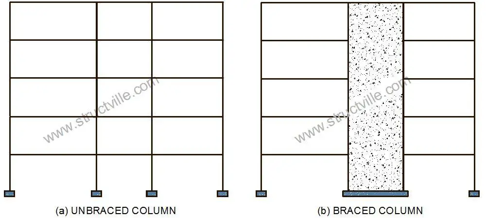
However, most concrete buildings are designed as braced structures. Unbraced structures are rare and are used only if there is a need for uninterrupted floor space.
Loads/Actions on Columns
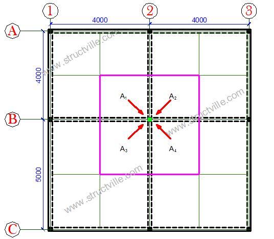
The major action effects on columns are compressive axial force, bending moment, and shear force. In the manual design of reinforced concrete columns, the design axial force can be obtained using the tributary area method or by summing up the support reactions from the beams supported by the column. The self-weight of the column should be included in the calculation of the design axial force.
In the tributary area method, the floor panels supported by the columns are divided into equal parts, and the load from each part transferred to the nearest column. The process is shown in Figure 2.
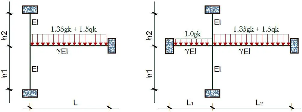
For the manual analysis of column design moment, sub-frames can be used to obtain the maximum design moment (see Figure 3). The recommendation is that you should consider the adjacent beams fully fixed, while you reduce their stiffness by half, because it will be an overestimation of the stiffness of the beams to consider all the ends fully fixed. (Details of this can be found in Reynolds and Steedman, 2005, Table 1, and Reynolds, Steedman, and Threlfall, 2008, Table 2.57).
Slenderness in the Design of Reinforced Concrete Columns
Clause 5.8.2 of EN 1992-1-1 deals with members and structures in which the structural behaviour is significantly influenced by second-order effects (e.g. columns, walls, piles, arches and shells). Global second-order effects are more likely to occur in structures with a flexible bracing system.
Column design in EC2 generally involves determining the slenderness ratio (λ), of the member and checking if it lies below or above a critical value λlim. If the column slenderness ratio lies below λlim, it can simply be designed to resist the axial action and moment obtained from elastic analysis, but including the effect of geometric imperfections. These are termed first-order effects. However, when the column slenderness exceeds the critical value, additional (second-order) moments caused by structural deformations can occur and must also be taken into account.
So in general, second order effects may be ignored if the slenderness λ is below a certain value λlim.
λlim = (20.A.B.C)/√n ——- (1)
where:
A = 1/(1 + 0.2ϕef) (if ϕef is not known, A = 0.7 may be used)
B = 1+ 2ω (if ω is not known, B = 1.1 may be used)
C = 1.7 – rm (if rm is not known, C = 0.7 may be used)
Where;
ϕef = effective creep ratio (0.7 may be used)
ω = Asfyd / (Acfcd); mechanical reinforcement ratio;
As is the total area of longitudinal reinforcement
n = NEd / (Acfcd); relative normal force
rm = M01/M02; moment ratio
M01, M02 are the first order end moments, |M02| ≥ |M01|
If the end moments M01 and M02 give tension on the same side, rm should be taken positive (i.e. C ≤ 1.7), otherwise negative (i.e. C > 1.7). For braced members in which the first-order moments arise only from or predominantly due to imperfections or transverse loading rm should be taken as 1.0 (i.e. C = 0.7):
Also, clause 5.8.3.1(2) of EC2 says that for biaxial bending, the slenderness criterion may be checked separately for each direction. Depending on the outcome of this check, second-order effects (a) may be ignored in both directions, (b) should be taken into account in one direction, or (c) should be taken into account in both directions.
Slenderness of isolated members
According to clause 5.8.3.2 of EC2, the slenderness ratio of an isolated member is defined as follows:
λ = l0/i —— (2)
where:
l0 is the effective length
i is the radius of gyration of the uncracked concrete section (i = h/√12 for rectangular sections)
Effective length of isolated members
From Figure 5.7 of EC2, examples of effective length for isolated members with constant cross-section are given as shown in Figure 4. This gives the examples of different buckling modes and corresponding effective lengths for isolated members.
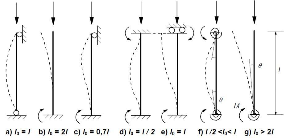
However, for compression members in regular braced frames, the slenderness criterion should be checked with an effective length l0 determined in the following way:
l0 = 0.5L √[(1 + k1/(0.45 + k1)) × (1 + k2/(0.45 + k2))] ——- (3)
Where;
k1, k2 are the relative flexibilities of rotational restraints at ends 1 and 2 respectively.
L is the clear height of the column between the end restraints
k = 0 is the theoretical limit for rigid rotational restraint, and k = ∞ represents the limit for no restraint at all. Since fully rigid restraint is rare in practice, a minimum value of 0.1 is recommended for k1 and k2.
According to Table 4.15 of Reynolds, Steedman and Threlfall (2008),
“In the above equations, k1 and k2 are the relative flexibilities of rotational restraint at nodes I and 2 respectively. If the stiffness of adjacent columns does not vary significantly (say, difference not exceeding 15% of the higher value), the relative flexibility may be taken as the stiffness of the column under consideration divided by the sum of the stiffness of the beams (or, for an end column, the stiffness of the beam) attached to the column in the appropriate plane of bending. Otherwise, the effective column stiffness should be taken as the sum of the stiffness of the columns above and below the node.
The stiffness of a member is 4EI/L for members fixed at the remote end, and 3EI/L for members pinned at the remote end, where I is the second moment of area of the cross-section allowing for the effect of cracking (for beams, 50% of the value for the uncracked section could be used), and L is the length of the member.
For flat slabs, the beam stiffness should be based on the dimensions of the column strip. At nodes where the beams are considered as nominally simply-supported, and at bases not designed to resist column moments, k should be taken as 10. At bases designed to resist column moments, k may be taken as 1.0”.
Methods of Analysis of Reinforced Concrete Columns
According to clause 5.8.5 (1), the methods of analysis include a general method, based on non-linear second order analysis and the following two simplified methods:
(a) Method based on nominal stiffness
(b) Method based on nominal curvature
The method of nominal curvature has been used in this article, which is mainly suitable for isolated members with a constant normal force.
Design Bending Moment of reinforced concrete columns
According to clause 5.8.8.2, the design moment is:
MEd = M0Ed + M2 —– (4)
where:
M0Ed is the 1st order moment, including the effect of imperfections,
M2 is the nominal 2nd order moment
The maximum value of MEd is given by the distributions of M0Ed and M2; the latter may be taken as parabolic or sinusoidal over the effective length.
Note: For statically indeterminate members, M0Ed is determined for the actual boundary conditions, whereas M2 will depend on boundary conditions via the effective length.
By differing first order end moments, M01 and M02 may be replaced by an equivalent first order end moment M0e:
M0e = 0.6M02 + 0.4M01 ≥ 0.4M02 ——–(5)
M01 and M02 should have the same sign if they give tension on the same side, otherwise opposite signs. Furthermore, |M02| ≥ |M01|.
The nominal second order moment M2 in Expression (4) is;
M2 = NEde2 ——- (6)
where:
NEd is the design value of axial force
e2 is the deflection = (1/r) l02/c
1/r is the curvature
l0 is the effective length
c is a factor depending on the curvature distribution
For constant cross-section, c = 10 (≈ π2) is normally used. If the first-order moment is constant, a lower value should be considered (8 is a lower limit, corresponding to constant total moment).
Simplified Design Steps when λ < λlim (Arya, 2009)
According to clause 5.8.3.1 of EC2, if the slenderness, λ, is less than λlim, the column should be designed for the applied axial load, NEd, and the moment due to first-order effects, MEd, being numerically equal to the sum of the larger elastic end moment, M02, plus any moment due to geometric imperfection, NEd.ei, as follows:
MEd = M02 + NEd.ei ——— (7)
Where;
ei is the geometric imperfection = (θil0/2)
θi is the angle of inclination and can be taken as 1/200 for isolated braced columns and l0 is the effective length (clause 5.2(7)).
According to clause 6.1(4) the minimum design eccentricity, e0, is h/30 but not less than 20 mm where h is the depth of the section.
Once NEd and MEd have been determined, the area of longitudinal steel can be calculated by strain compatibility using an iterative procedure.. However, this approach may not be practical for everyday design and therefore The Concrete Centre has produced a series of design charts, similar to those in BS 8110:Part 3, which can be used to determine the area of longitudinal steel.
Curvature
According to clause 5.8.8.3 of EC2, for members with constant symmetrical cross sections (including reinforcement), the following relation may be used:
1/r = Kr.Kϕ.1/r0 ———(8)
where:
Kr is a correction factor depending on axial load
Kϕ is a factor for taking account of creep
1/r0 = εyd/(0.45d)
εyd = fyd/Es
d is the effective depth
Es is the elastic modulus of steel = 200 kN/mm2
However, if all reinforcement is not concentrated on opposite sides, but part of it is distributed parallel to the plane of bending, d is defined as
d = (h/2) + is ——— (9)
where is is the radius of gyration of the total reinforcement area.
Kr = (nu – n) / (nu – nbal) ≤ 1 ——— (10)
where:
n = NEd /(Acfcd), relative axial force
NEd is the design value of axial force
nu = 1 + ω
nbal is the value of n at maximum moment resistance; the value 0.4 may be used
ω = Asfyd /(Acfcd)
As is the total area of reinforcement
Ac is the area of concrete cross-section
The effect of creep should be taken into account by the following factor:
Kϕ = 1 + βϕef ≥ 1.0
where:
ϕef is the effective creep ratio
β = 0.35 + fck/200 – λ/150
λ is the slenderness ratio
Simplified Design Steps of Columns when λ > λlim (Arya, 2009)
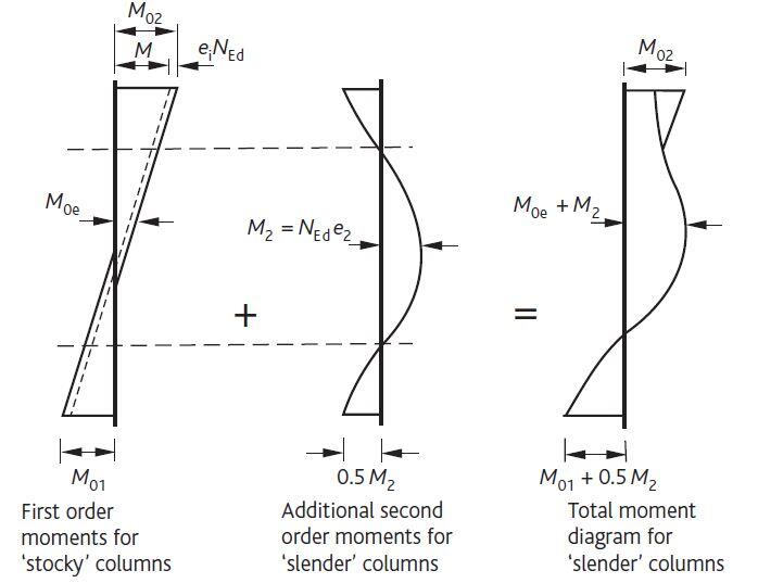
When λ > λlim, critical conditions may occur at the top, middle or bottom of the column. The values of the design moments at these positions are, respectively (see Figure 5):
(i) M02
(ii) M0Ed + M2
(iii) M01 + 0.5M2
M0Ed is the equivalent first-order moment including the effect of imperfections at about mid-height of the column and may be taken as M0e as follows:
M0e = (0.6M02 + 0.4M01) ≥ 0.4M02 ———(11)
Where;
M01 and M02 are the first order end moments including the effect of imperfections acting on the column and M02 is the numerically larger of the elastic end moment acting on the column i.e.
|M02| > |M01|
M2 is the nominal second order moment acting on the column and is given by
M2 = NEd.e2
Where;
NEd is the design axial load at ULS
e2 is the deflection = (1/r) (l02)/10
Biaxial Bending of Reinforced Concrete Columns
According to clause 5.8.9 of EC2, separate design in each principal direction, disregarding biaxial bending, may be made as a first step. Imperfections need to be taken into account only in the direction where they will have the most unfavourable effect.
No further check is necessary if the slenderness ratios satisfy the following two conditions
λy/λz ≤ 2.0 and λz/λy ≤ 2.0 ——–(12)
and if the relative eccentricities ey/h and ez/b satisfy one the following conditions:
(ey/heq)/(ez/beq) ≤ 0.2 or (ez/beq)/(ey/heq) ≤ 0.2 ——— (13)
where:
b, h are the width and depth of the section
beq = iy.√12 and heq = iz.√12 for an equivalent rectangular section
λy and λz are the slenderness ratios l0/i with respect to the y- and z-axis respectively
iy, iz are the radii of gyration with respect to y- and z-axis respectively
ez = MEd,y /NEd; eccentricity along z-axis
ey = MEd,z /NEd; eccentricity along y-axis
MEd,y is the design moment about y-axis, including the second-order moment
MEd,z is the design moment about z-axis, including second order moment
NEd is the design value of axial load in the respective load combination
If the condition of Expression (12 and 13) is not fulfilled, biaxial bending should be taken into account including the 2nd order effects in each direction (unless they may be ignored according to clauses 5.8.2 (6) or 5.8.3 of EC2). In the absence of an accurate cross-section design for biaxial bending, the following simplified criterion may be used
(MEdz/MRdz )a + (MEdy/MRdy)a ≤ 1.0 ——–(14)
where:
MEd,i is the design moment around the respective axis, including a 2nd order moment.
MRd,i is the moment resistance in the respective direction
a is the exponent;
for circular and elliptical cross-sections: a = 2
For rectangular sections, see Table 1;
Table 1: Values of ‘a’ exponent for rectangular sections
| NEd/NRd | 0.1 | 0.7 | 1.0 |
| a | 1.0 | 1.5 | 2.0 |
Linear interpolation can be used for intermediate values
NEd is the design value of axial force
NRd = Acfcd + Asfyd, design axial resistance of section.
Where:
Ac is the gross area of the concrete section
As is the area of longitudinal reinforcement
Design example of reinforced concrete columns
Design a 230 x 230 mm biaxially loaded reinforced concrete column with a clear height of 4050 mm. The forces acting on the column are given below. fck = 25 MPa, fyk = 460 Mpa, Concrete cover = 35 mm
Design axial force;
NEd = 399.887 kN
Elastic Moments
X – direction: M01 = 13.185 kNm; M02 = – 6.592 kNm
Z – direction: M01 = 7.138 kNm; M02 = – 3.569 kNm
Clear column height = 4050 mm
The effective height of the column (l0) (see Ubani, 2017)
In the x-direction; l0 = 2861.5 mm
In the z-direction; l0 = 2924.34 mm
Radius of gyration i = h/√12 = 230/√12 = 66.395
λx = 2861.5/66.395 = 43.098
λz = 2924.34/66.395 = 44.044
Critical Slenderness for the x-direction
λlim = (20.A.B.C)/√n
A = 0.7
B = 1.1
C = 1.7 – M01/M02 = 1.7 – (-6.592/13.185) = 2.199
n = NEd/(Acfcd)
NEd = 399.887 × 10³ N
Ac = 230 × 230 = 52900 mm2
fcd = (αccfck)/1.5 = (0.85 × 25)/1.5 = 14.166 N/mm2
n = (399.887 × 10³)/(52900 × 14.166) = 0.5336
λlim = (20 × 0.7 × 1.1 × 2.199 )/√0.5336 = 46.359
43.098 < 46.359, second order effects need not to be considered in the x-direction
Critical Slenderness for the z-direction
A = 0.7
B = 1.1
C = 1.7 – M_01/M_02 = 1.7 – ((-3.569)/7.138) = 2.2
n = NEd/(Acfcd) = 0.5336
44.044 < 46.381, second order effects need not to be considered in the z – direction
Design Moments (x-direction)
M01 = 6.592 kNm, M02 = 13.185 kNm
e1 is the geometric imperfection = (θi l0/2) = (1/200 × 2862/2) = 7.155 mm
Minimum eccentricity e0 = h/30 = 230/30 = 7.667mm. Since this is less than 20mm, take minimum eccentricity = 20mm
Minimum design moment = e0NEd = 20 × 10-3 × 399.87 = 7.9974 kNm
First order end moment M02 = MTop + eiNEd
eiNEd = 7.155 × 10-3 × 399.87 = 2.861 kNm
M02 = MTop + eiNEd = 13.185 + 2.861 = 16.046 kNm
Longitudinal Steel Area
d2 = Cnom + ϕ/2 + ϕlinks = 35 + 8 + 8 = 51 mm
d2/h = 51/230 = 0.2217
Reading from chart No 1; d2/h = 0.2;
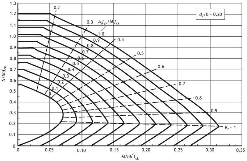
MEd/(fck bh2) = (16.046 × 10⁶)/(25 × 230 × 2302) = 0.0527
NEd/(fckbh) = (399.88 × 10³)/(25 × 230 × 230) = 0.302
From the chart, (Asfyk)/(bhfck) = 0.15
Area of longitudinal steel required (As) = (0.15 × 25 × 230 × 230)/460 = 431.25 mm2
As,min = 0.10 NEd/fyd = (0.1 × 399.887)/400 = 0.099 mm2 < 0.002 × 230 × 230 = 105.8 mm2
As,max = 0.04bh = 2116 mm2
Provide 4Y16mm (As,prov = 804 mm2) Ok
Design Moments (z-direction)
M01 = 3.569 kNm, M02 = 7.138 kNm
e1 is the geometric imperfection = (θi l0/2) = (1/200 × 2865/2) = 7.1625 mm
Minimum eccentricity e0 = h/30 = 230/30 = 7.667mm. Since this is less than 20 mm, take minimum eccentricity = 20 mm
Minimum design moment = e0NEd = 20 × 10-3 × 399.87 = 7.9974 kNm
First order end moment M02 = MTop + eiNEd
eiNEd = 7.1625 × 10-3 × 399.87 = 2.864 kNm
M02 = MTop + eiNEd = 7.138 + 2.864 = 10.002 kNm
Longitudinal Steel Area
d2 = Cnom + ϕ/2 + ϕlinks = 35 + 8 + 8 = 51 mm
d2/h = 51/230 = 0.2217
Reading from chart No 1; d2/h = 0.2;
MEd/(fck bh2) = (10.002 × 10⁶)/(25 × 230 × 2302) = 0.03288
NEd/(fckbh) = (399.88 × 10³)/(25 ×230 × 230) = 0.302
From the chart, (Asfyk)/(bhfck) = 0.05
Area of longitudinal steel required (As) = (0.05 × 25 × 230 × 230)/460 = 143.75 mm2
Provide 4Y16mm (As,prov = 804 mm2)
Biaxial Effects
Check if λy/λz ≤2.0 and λz/λy ≤ 2.0
43.098/44.044 = 0.9785 < 2.0, and 44.044/43.098 = 1.0219 < 2.0
Furthermore, let us also check;
(ey/heq)/(ez/beq) ≤ 0.2 or (ez/beq)/(ey/heq) ≤ 0.2
ex = MEd,x/NEd = (16.046 × 10⁶)/(399.887 × 103) = 40.126 mm
ez = MEd,z/NEd = (10.002 × 10⁶)/(399.887 × 103) = 25.012 mm
heq = beq = i.√12 = 66.395 × √12 = 230 mm
ex/heq ÷ ez/beq = 40.126/230 ÷ 25.012/230 = 1.6042 > 0.2
Therefore we have to check for biaxial bending;
(Asfyk)/(bhfck) = (804 × 460)/( 25 × 230 × 230) = 0.279
Therefore from the chart; MRd/(fckbh2) = 0.08
MRd = 0.08 × 25 × 230 × 2302 = 24.334 kNm
NRd = Acfcd + Asfyd
NRd = (2302 × 14.1667) + (804 × 400) = 1071.0 kN
NEd/NRd = 399.88/1071.0 = 0.373
By linear interpolation from Table 1, a = 1.0 + (0.373 – 0.1 )/(0.7 – 0.1) × (1.5 – 1.0)= 1.2275
(MEdz/MRdz )a + (MEdy/MRdy)a ≤ 1.0
(16.046/24.334)1.2275 + (10.002/24.334)1.2275 = 0.599 + 0.3357 = 0.9347 < 1.0. This is ok
Links
Minimum size = 0.25ϕ = 0.25 × 16 = 4mm < 6mm
We are adopting Y8mm as links
Spacing adopted = 200mm less than min{b, h, 20ϕ, 400mm}




Wow! An Engineer indeed! Thanks a lot for the very detailed and correct design. It has helped me a lot.
Top content
Dear,
You didn’t provide the final detail reinforcement.
you got 4Y16 in both sides (x and Z), does it mean you provide a total of 8Y16 ?
I need all the Questions and answers under columns
Its layout of reinforced concrete columns is the main topic of this blog post. It includes thorough details regarding the design process, including the factors, calculations, and considerations that must be made. patio builders fredericksburg va Overall, it is a useful tool for anyone working in structural engineering or for anyone curious about the design ideas behind reinforced concrete columns.
GREAT WORK,WITH TOP QUALITY.THANKS SO MUCH
Ing Tom More Mwanje From Uganda
You’ve interchanged Mo1 and Mo2 while computing the design moment Med in the z-direction
Otherwise very helpful, especially the check for bi-axial bending