The slab-on-grade, which includes industrial ground floors, can be defined as a slab continuously supported by ground with an area of more than twice the area required to support the imposed loads. The primary design objectives in industrial ground floor slabs are to carry the intended loads and to avoid surface cracking.
The slab may be plain or reinforced and may include stiffening elements such as ribs and hidden beams. The reinforcement may be provided for structural purposes or for the control of the effects of shrinkage and temperature changes.
Industrial ground floor slabs are essential components of industrial buildings and warehouses. In order for manufacturing equipment and forklifts to function properly, the slab must be uniformly flat and joints must be relatively level without excessive movements. The growth of the industry has necessitated the use of larger and heavier machinery and storage facilities.
In addition, the evolution of construction practices, such as the trend toward larger floor slabs with fewer joints, the use of high early-strength cement, and the increase in the use of admixtures, have all contributed to the rise in the cracking and curling of these slabs.
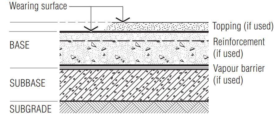
The typical layers in an industrial ground floor slab is shown in Figure 1;
The manner in which uniform loads are stacked in warehouses causes some cracking in the aisles between loaded areas. The predominant types of cracking in aisles fall into two categories. The first type is longitudinal, while the second is transverse. Transverse cracking is directly attributable to shrinkage, whereas longitudinal cracking is caused by the way external loads are stacked in warehouses.
In warehouses, heavy uniform loads are typically distributed over a portion of the slab, typically around the columns, leaving clear aisles in the middle of these columns.
The requirements for concrete industrial ground floors include the following:
- The floor should remain serviceable, assuming planned maintenance and no gross misuse or overloading.
- The floor must be able to carry the required static point loads, uniformly distributed loads and dynamic loads, without unacceptable deflection, cracking, settlement or damage to joints.
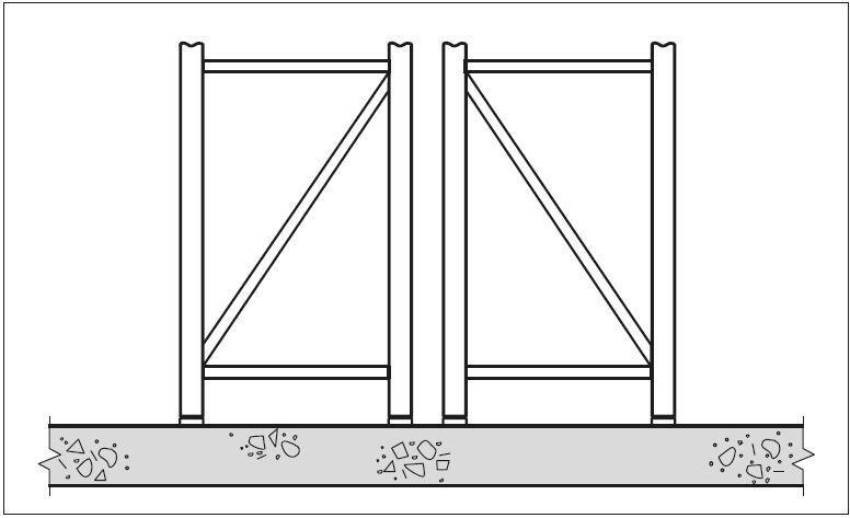
- Joint layouts should take into account the location of racking uprights or mezzanine floor columns.
- Joints should be robust in both design and construction.
- Joints and reinforcement should be detailed to minimise the risk of cracking.
- The floor surface should have suitable surface regularity.
- The floor surface should have suitable abrasion, chemical and slip resistance.
- The floor should have the required type of finish.

Warehouse Equipment and Floor Loading
Point loads from pallet racking, accompanying materials handling equipment (MHE), and mezzanines are frequent loads on warehouse floors. Other loads come from uniformly distributed loads (UDL) like palletized products or bulk loose materials, as well as line loads like interior walls and floor railing systems.

In the design of industrial ground floors, point loads are usually the most critical for design, and reliance should not be placed solely on the commonly specified uniformly distributed loads (UDLs). In all cases, the design must be based on anticipated loads from all types of equipment and other loads, and the specifier must account for the floor’s potential future uses.
It is reasonable to anticipate that taller structures will be able to support greater loads, such as those imposed by pallet racking. Point loads from pallet racking and mezzanines are treated as static loads, whereas mobile heavy equipment (MHE) is treated as a dynamic load that requires greater design safety factors.
Design of Industrial Ground Floor Slab
For the commonly encountered point loads on industrial ground floor slabs from storage shelving, mezzanines, and materials handling equipment (MHE), there are two possible modes of ultimate strength failure:
- flexure, and
- punching
The design of slabs for flexure under point loads at the ultimate limit state (ULS) is based on yield line theory, which necessitates sufficient plasticity to assume plastic behaviour. Clearly, sufficient rotation capacity of the sagging yield lines is required in order to mobilise the hogging moment capacity.
At the ULS, it is assumed that the bending moment along the sagging (positive moment) yield lines is the full plastic (or residual post-cracking) value. As the avoidance of cracks on the upper surface is a primary requirement for serviceability, the bending moment of the slab along the hogging yield lines is limited to the design cracking moment of the concrete, albeit with the partial safety factor appropriate to the ULS.
According to TR34, this is not a true ULS because the floor will not have collapsed, and the design process is meeting a serviceability requirement instead. Therefore, there are no separate checks for design serviceability. The design of the slab against punching shear around concentrated loads is based on Eurocode 2 for suspended slabs. It is taken into account that a portion of the load will be transferred through the slab to the ground.
Line loads and uniformly distributed loads are evaluated using an elastic analysis based on Hetenyi’s Beams on Elastic Foundation. The minimum recommended slab thickness for a ground-supported slab is 150 millimetres.
The designer must account for the thickness reduction caused by mat wells, induction loops, guide wires, and other features. There are practical limitations on how much concrete can be poured in one day, so most floors have joints. In most instances, the critical loading condition is a point load close to a slab panel joint.
In all designs, the load-bearing capacity of the floor alongside joints must be evaluated. This capacity will depend heavily on the joint mechanism’s ability to transfer load to the opposite side of the joint. This is especially true for MHE, which cannot be positioned away from joints, unlike static loads.
Worked Examples
Quadruple Internal Point Loads
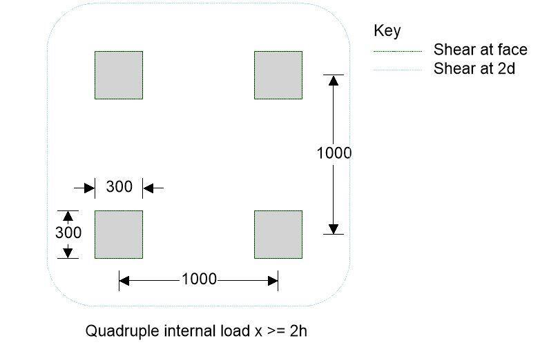
Verify the capacity of a 200mm thick concrete industrial ground floor slab subjected to a quadruple internal 300 x 300 point load in accordance with TR34, 4th Edition 2013;
Permanent load; Gk = 45.0 kN
Variable load; Qk = 20.0 kN
Dynamic load; Dk = 30.0 kN
Slab details
Reinforcement type; Fabric
Concrete class; C25/30
Slab thickness; h = 200 mm
Fabric reinforcement type; A393
Characteristic strength of reinforcement; fyk = 500 N/mm2
Area of top steel provided; As,prov = 393 mm2/m
Diameter of reinforcement; fs = 10 mm
Nominal cover; cnom_b = 50 mm
Effective depth of reinforcement; d = 0.75h = 150 mm
Partial safety factors
Concrete (with or without fibre); γc = 1.50
Reinforcement (bar or fabric); γs = 1.15
Permanent; γG = 1.20
Variable; γQ = 1.50
Dynamic loads; γD = 1.60
Subgrade reaction
Modulus of subgrade reaction; k = 0.030 N/mm3
Properties of Concrete
Characteristic compressive cylinder strength; fck = 25 N/mm2
Characteristic compressive cube strength; fcu = 30 N/mm2
Mean value of compressive cylinder strength; fcm = fck + 8 N/mm2 = 33 N/mm2
Mean value of axial tensile strength; fctm = 0.3 N/mm2 × (fck)2/3 = 2.6 N/mm2
Flexural tensile strength; fctd,fl = fctm × (1.6 – h /1000) / γc = 2.4 N/mm2
Design concrete compressive strength (cylinder); fcd = fck / γc = 16.7 N/mm2
Secant modulus of elasticity of concrete; Ecm = 22 kN/mm2 × [fcm/10 ]0.3 = 31 kN/mm2
Poisons ratio; v = 0.2
Radius of relative stiffness (Eqn. 20); l = [Ecmh3 / (12(1 – v2) × k)]0.25 = 924 mm
Characteristic of system (Eqn. 33); l = (3k / (Ecmh3))0.25 = 0.773 m-1
Moment capacity
Negative moment capacity (Eqn. 2); Mn = Mun = fctd,fl × (h2/6) = 16.0 kNm/m
Positive moment capacity (Eqn. 2); Mp = Mun = 16.0 kNm/m
Loading – Quadruple internal 300 x 300 point load
Loading length; ll = 300mm
Loading width; lw = 300mm
Distance x; x = 1000mm
Distance y; y = 1000mm
Permanent load; Gk = 45.0 kN
Variable load; Qk = 20.0 kN
Dynamic load; Dk = 30.0 kN
Contact radius ratio
Equivalent contact radius ratio; a = [(ll × lw) / π]0.5 = 169.3 mm
Radius ratio; a/l = 0.183
Ultimate capacity under single internal concentrated loads
For a/l equal to 0 (Eqn. 21); Pu_0 = 2π(Mp + Mn) = 200.6 kN
For a/l equal to 0.2 (Eqn. 22); Pu_0.2 = 4π(Mp + Mn) / [1 – (a / (3 × l))] = 427.2 kN
Thus for a / l equal to 0.183; Pu = min(Pu_0.2, Pu_0 + (Pu_0.2 – Pu_0) × (a / (l × 0.2))) = 408.2 kN
4 No. individual; Pu_4x1 = 4Pu = 1632.6 kN
Ultimate capacity under dual internal concentrated loads
For a/l equal to 0 (Eqn. 27); Pu_0 = [2π + (1.8 × min(x, y) / l)] × [Mp + Mn] = 262.7 kN
For a/l equal to 0.2 (Eqn. 28);Pu_0.2 = [4π / (1 – (a / (3 × l))) + 1.8 × min(x, y) / (l – (a/2))] × [Mp + Mn] = 495.7 kN
Thus for a / l equal to 0.183; Pu = min(Pu_0.2, Pu_0 + (Pu_0.2 – Pu_0) × (a / (l × 0.2))) = 476.1 kN
2 No. dual; Pu_2x2 = 2 × Pu = 952.2 kN
Ultimate capacity under quadruple internal concentrated loads
For a/l equal to 0 (Eqn. 29); Pu_0 = [2π + 1.8 × (x + y) / l] × [Mp + Mn] = 324.9 kN
For a/l equal to 0.2 (Eqn. 30); Pu_0.2 = [4π / (1 – (a / (3 × l))) + 1.8(x + y) / (l – (a / 2))] × [Mp + Mn] = 564.1 kN
Thus for a / l equal to 0.183; Pu = min(Pu_0.2, Pu_0 + (Pu_0.2 – Pu_0) × (a / (l × 0.2))) = 544.0 kN
quadruple;Pu_1x4 = Pu = 544.0 kN
Ultimate load capacity for 4 No. loads; Pu = min(Pu_4x1, Pu_2x2, Pu_1x4) = 544.0 kN
Check ultimate load capacity of slab
Number of loads; N = 4
Loading applied to slab; Fuls = N × [(GkγG) + (QkγQ) + (DkγD)] = 528.0 kN
Utilisation; Fuls / Pu = 0.971
PASS – Total slab capacity exceeds applied load
Punching shear at the face of the loaded area
Shear factor; k2 = 0.6(1 – fck / 250 N/mm2) = 0.54
Length of perimeter at face of loaded area; u0 = 8 (ll + lw) = 4800 mm
Shear stress at face of contact area; vmax = 0.5k2fcd = 4.500 N/mm2
Maximum load capacity in punching; Pp,max = vmax × u0 × d = 3240.0 kN
Utilisation; Fuls / Pp,max = 0.163
PASS – Total slab capacity in punching at face of loaded area exceeds applied load
Punching shear at the critical perimeter
Shear factor; ks = min(1 + (200mm / d)0.5, 2) = 2.00
Minimum shear stress at 2d from face of load; vRd,c,min = 0.035ks3/2 × (fck)0.5 = 0.495 N/mm2
Ratio of reinforcement by area in x-direction; rx = As,prov / d = 0.00262
Ratio of reinforcement by area in y-direction; ry = As,prov / d = 0.00262
Reinforcement ratio; r1 = (rx × ry)0.5 = 0.00262
Maximum shear stress at 2d from face of load; vRd,c = max(0.18 × ks / γc × (100 × r1 × fck )1/3, vRd,c,min) = 0.495 N/mm2
Length of perimeter at 2d from face of load; u1 = 2 × (lw + y + ll + x + 2π × d) = 7085 mm
Max. load capacity in punching at 2d from face; Pp = vRd,c × u1 × d = 526.0 kN
Ground reaction (cl.7.10.2); Rp = 1.4 × (d / l)2 × Fuls + 0.47 × (ll + x + lw + y) × d × Fuls / l2 = 132.9 kN
Total imposed shear load; Fuls_total = Fuls – Rp = 395.1 kN
Utilisation; Fuls_total / Pp = 0.751
PASS – Total slab capacity in punching at 2d from face of loaded area exceeds applied load
Design Summary
| Description | Unit | Provided | Required | Utilisation | Result |
| Slab capacity in flexure | kN | 544.0 | 528.0 | 0.971 | PASS |
| Shear at face | kN | 3240.0 | 528.0 | 0.163 | PASS |
| Shear at 2d | kN | 526.0 | 395.1 | 0.751 | PASS |
Uniformly Distributed Load
Verify the capacity of a 150mm thick concrete industrial ground floor slab to support a uniformly distributed load of 45 kN/m2 in accordance with TR34, 4th Edition 2013;
Slab details
Reinforcement type; Fabric
Concrete class; C25/30
Slab thickness; h = 150 mm
Fabric reinforcement type; A252
Characteristic strength of reinforcement; fyk = 500 N/mm2
Area of top steel provided; As,prov = 252 mm2/m
Diameter of reinforcement; fs = 8 mm
Nominal cover; cnom_b = 50 mm
Effective depth of reinforcement; d = 0.75 × h = 112 mm
Partial safety factors
Concrete (with or without fibre); γc = 1.50
Reinforcement (bar or fabric); γs = 1.15
Permanent; γG = 1.20
Variable; γQ = 1.50
Dynamic loads; γD = 1.60
Subgrade reaction
Modulus of subgrade reaction; k = 0.030 N/mm3
Strength properties for concrete
Characteristic compressive cylinder strength; fck = 25 N/mm2
Characteristic compressive cube strength; fcu = 30 N/mm2
Mean value of compressive cylinder strength; fcm = fck + 8 N/mm2 = 33 N/mm2
Mean value of axial tensile strength; fctm = 0.3 N/mm2 × (fck)2/3 = 2.6 N/mm2
Flexural tensile strength; fctd,fl = fctm × (1.6 – h / 1000) / γc = 2.5 N/mm2
Design concrete compressive strength (cylinder); fcd = fck / γc = 16.7 N/mm2
Secant modulus of elasticity of concrete; Ecm = 22 kN/mm2 × [fcm/ 10 ]0.3 = 31 kN/mm2
Poisons ratio; v = 0.2
Radius of relative stiffness (Eqn. 20); l = [Ecm × h3 / (12 × (1 – n2) × k)]0.25 = 745 mm
Characteristic of system (Eqn. 33); l = (3 × k / (Ecm × h3))0.25 = 0.959 m-1
Moment capacity
Negative moment capacity (Eqn. 2); Mn = Mun = fctd,fl × (h2 / 6) = 9.3 kNm/m
Positive moment capacity (Eqn. 2); Mp = Mun = 9.3 kNm/m
Load 1 – UDL 45 kN/m2
Working load capacity of UDL
UDL; Uk = 45.0 kN/m2
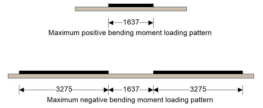
Critical aisle width; lcrit = π / (2 × l) = 1637 mm
Loaded width of single UDL (max positive moment); lload_p = π / (2 × l) = 1637 mm
Loaded width of dual UDL (max nagative moment); lload_n = π / l = 3275 mm
Working load capacity of slab; q = 5.95 × l2 × Mn = 50.9 kN/m2
Utilisation; Uk / q = 0.884
PASS – Total slab capacity exceeds applied load
Design Summary
| Description | Unit | Provided | Required | Utilisation | Result |
| Slab capacity in flexure | kN/m2 | 50.9 | 45.0 | 0.884 | PASS |




Excellent work , thanks for sharing!
Would you be so kind to explain me how do you obtain p in your design which consisted on the critical aisle formula etc …
Thanks in advance
Pantelis
The ‘p’ actually stands for ‘pi’ (π). It has been corrected accordingly in the text.
Why is Mp = Mn? TR34 is vague on how these should be evaluated.
I agree, it is not clear. I have the 2003 edition and for steel fibre reinforced slabs it defines Mp as the residual (post-cracking) positive moment capacity. Furthermore, in Appendix E, Mp is based on the area of the flexural reinforcement. In both cases Mp is less than Mn. So if we use Mp = Mn for plain concrete slabs (or those with crack control steel only, as in the examples above), then we get a higher flexural capacity than we would for fibre or mesh reinforced slabs, which doesn’t make sense. If Mp is the post-cracking residual moment capacity I believe for plain slabs it should be taken as zero. But you are right, TR-34 is not clear on this point.
I have the 2003 edition of TR-34. For fibre reinforced slabs Mp is defined as the residual (post-cracking) positive bending moment capacity, which is less that the moment that causes flexural cracking (since the value of Rc,3 in equation 9.8 is less than 1). Hence, for plain concrete slabs (or with crack control reinforcement only as in the examples above) if you use (Mp + Mn) to calculate the flexural capacity you get a higher value than you would for a steel fibre reinforced slab, which, intuitively, doesn’t make sense. For plain concrete slabs should we not therefore take Mp as zero (i.e. no post cracking residual moment capacity) and use Mn only to calculate flexural capacity?
Agree, Mp=0 for plain concrete.