In construction, scaffolds play an important role as temporary structures facilitating access to elevated work areas and providing safe work platforms. Typically assembled from steel or aluminium alloy tubes connected through clips or couplings, these structures enable workers to reach heights otherwise inaccessible while ensuring their safety during various building operations.
The design and construction of all scaffolds must adhere strictly to the established minimum requirements stipulated in both the Work at Height Regulations 2005 and BS EN 12811-1: 2003 – Temporary works equipment. Scaffolds. Performance requirements and general design. Following these regulations and standards is paramount for ensuring the structural integrity, stability, and overall safety of scaffolds, ultimately protecting the well-being of workers relying on them during construction projects.
Types of Scaffolding
There are different types of scaffolds, each suited to different construction needs and budgets. Some of the common types of scaffolds are;
1. Putlog Scaffolds: This design employs a single row of vertical supports (standards) arranged at a pre-determined distance from the wall to accommodate the desired platform width. Horizontal members (ledgers) connect the standards, further secured to the building structure with cross-members known as putlogs. Primarily utilized for brick construction, this scaffold grows incrementally alongside the building’s rising height.
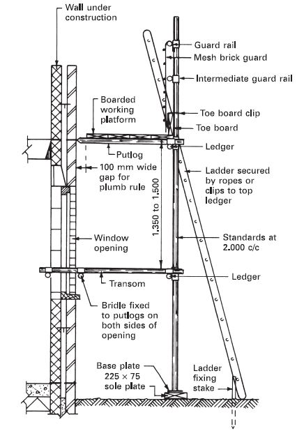
2. Independent Scaffolds: Featuring two rows of standards interconnected by transoms (horizontal cross-members), independent scaffolds stand independently without relying on the building for support. This makes them ideal for framed structures. Secure ties bind the scaffold to the building at regular intervals, typically every 3.6 meters vertically and 6 meters horizontally. Attachment methods include bridles (horizontal tubes bearing on the wall’s interior), reveal pin tubes within openings, or, in the absence of suitable openings, raking tubes inclined towards the building from the ground.

3. Slung Scaffolds: Slung scaffolds are suspended by wire ropes or chains and lack inherent raising or lowering mechanisms. They primarily access high ceilings or undersides of elevated roofs. As a result, secure anchorage points, often utilizing the roof’s structural members above the designated work area are very important for their support.
A minimum of six evenly spaced suspension ropes or chains, securely fastened at both ends, is standard practice. Platforms, constructed similarly to conventional scaffolds with ledgers, transoms, and timber boards, require guardrails and toe boards for safety. For platforms exceeding 2.4 meters x 2.4 meters, stress analysis of supporting tubular components is recommended.
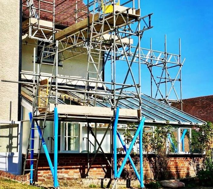
4. Truss-Out Scaffolds: This variation of the tied independent scaffold relies solely on the building for support, employed in situations where constructing a conventional ground-level scaffold is impractical or unfavourable. The projecting supporting structure, known as the truss-out, anchors to the building using adjustable struts secured internally between the floor and ceiling, from which cantilever tubes extend. Standard right-angle couplers are utilized except for securing rakers. The remaining scaffold construction follows the format of conventional independent scaffolds.

5. Suspended Scaffolds (Outrigger Cantilever Type): This configuration features a working platform suspended from supports such as outriggers cantilevering over a building’s upper edge. In this form, they serve as temporary access to the building facade for cleaning or light maintenance. Many modern tall structures incorporate suspension tracks either within the fascia or upper edge beam or a cradle suspension track is fixed to the flat roof, supporting a manual or powered trolley with retractable davit arms that hold the suspended working platform or cradle.

All suspended cradles must comply with the minimum platform board, guardrail, and toe board requirements mandated by the Work at Height Regulations 2005. Cradles can be single units or grouped to form a continuous platform, connected at their abutment ends with hinges.
6. Mobile Tower Scaffolds: Primarily used by painters and maintenance personnel, these scaffolds provide quick and easy access to ceilings by offering a movable working platform. Essentially, they are square towers constructed from scaffold tubes mounted on braked wheels. Users access the platform via short opposing inclined ladders or a single inclined ladder within the tower base area.

7. Birdcage Scaffold: For extensive, high-level work areas, birdcage scaffolds offer a comprehensive solution. These structures employ a grid-like arrangement of vertical supports (standards), horizontal connectors (ledgers), and cross-members (transoms) to support a solid working platform at the desired height. Stability is paramount, necessitating close placement of standards (not exceeding 2.4 meters apart) and adequate bracing throughout the scaffold.
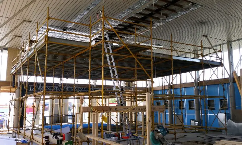
8. System scaffolds: This type of scaffold provides a modern alternative to traditional steel tube scaffolds. Utilizing innovative interlocking connections instead of loose couplers, they offer ease of erection, adaptability, and assembly/disassembly capabilities even for semi-skilled personnel. Notably, their design inherently adheres to the Work at Height Regulations 2005, ensuring proper handrail placement, lift heights, and other safety measures. An additional benefit is the elimination of internal cross-bracing, creating a clear walkthrough space on all levels. However, depending on the specific construction, facade bracing may still be necessary.

Materials for Scaffolding
The choice of material for scaffolding is multifaceted, influenced by factors like weight, strength, deflection characteristics, and corrosion resistance. There are four prevalent types of materials used in scaffolding:
- tubular steel,
- tubular aluminium alloy,
- timber, and
- bamboo.
Tubular Steel
British Standard 1139 sets guidelines for both welded and seamless steel tubes, typically measuring 48mm in outer diameter with a 38mm bore. Galvanization offers protection against corrosion, while ungalvanized options require post-use treatments like painting or oil baths. Steel tubes are nearly three times heavier than their aluminium counterparts. Steel boasts superior strength, enabling longer spans compared to aluminium due to less deflection (approximately one-third that of aluminium).
Tubular Aluminum Alloy
Seamless tubes of aluminium alloy with a 48mm outer diameter are specified in BS 1139. Aluminium generally doesn’t require protective treatment unless exposed to specific elements like damp lime, wet cement, or seawater. In such cases, a bitumastic paint coating before use is recommended. A significant advantage of aluminium is its lightweight nature, offering easier manoeuvrability and setup.
Timber
While less frequently employed in the UK, timber remains a prevalent choice in many developing countries for temporary scaffolding structures. Structural-quality softwood is utilized in either putlog or independent configurations. Unlike metal scaffolds with coupling fittings, timber members are traditionally joined together with wire or rope.
Bamboo
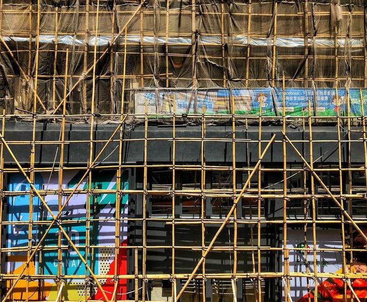
Unlike its steel counterpart, bamboo scaffolding boasts an eco-friendly advantage. It is a fast-growing renewable resource, with some species reaching maturity in as little as five years. This rapid growth rate makes it a sustainable alternative to steel, which requires significant energy and resources to produce.
Additionally, bamboo scaffolding is biodegradable, decomposing naturally after use. Bamboo’s unique properties make it surprisingly well-suited for scaffolding. Its high tensile strength allows it to support significant weight, while its natural flexibility makes it adaptable to various shapes and geometries.
The selection of scaffolding material hinges on various project-specific considerations. Steel’s strength and stability make it ideal for heavy-duty tasks and longer spans, while aluminium’s lightweight properties offer advantages in portability and ease of use. Timber, though less common in some regions, presents a traditional and potentially cost-effective option in suitable settings.
Scaffold boards
Scaffold boards are important components of scaffolds used to provide safe working platforms within the scaffold structure. They are expected to adhere to the specifications outlined in BS 2482. Boards must be constructed from specified softwoods, measuring 225 mm x 38 mm in cross-section and with a maximum length of 4.800 meters.
To prevent splitting, the ends of each board are required to be bound with a minimum of 25 mm wide x 0.9 mm thick galvanized hoop iron. This reinforcement extends at least 150 mm along each edge and is secured with at least two fixings per end. The specified strength of the boards ensures they can safely support a uniformly distributed load of 6.7 kN/m2 when supported at 1.2m intervals.
Scaffold Fittings
British Standard dictates the specifications for both steel and aluminium alloy scaffolding fittings, ensuring consistency and reliability across materials. These fittings typically allow for connections between various metal tubes unless otherwise specified by the manufacturer. Here’s a breakdown of key fittings used in metal scaffolding:
- Double Coupler: The primary load-bearing component, essential for connecting ledgers to standards.
- Swivel Coupler: Composed of two joined single couplers, enabling rotation for connecting tubes at any angle.
- Putlog Coupler: Specifically designed for attaching putlogs or transoms to horizontal ledgers.
- Base Plate: Distributes weight from the standard’s foot onto a sole plate or firm ground. Variations with threaded spigots cater to uneven terrain.
- Split Joint Pin: Expands to grip and join tubes end-to-end.
- Reveal Pin: Fits into tube ends to create adjustable struts.
- Putlog End: Converts a standard tube into a putlog using a flat plate attachment.

Stabilisers, Outriggers, or Diagonal Bracings
An optional attachment that can be adjusted to ensure ground contact where the surface is uneven. They should be attached securely to enable direct transfer of loads without slipping or rotating.
Structural Design of Scaffolds
The structural design of a scaffold system is very important for its functionality and safety. It addresses the optimal size, shape, and configuration of each component to guarantee the structure’s ability to withstand anticipated loads and external forces. By meticulously considering these details, the design mitigates excessive deflection, ensures overall stability, and prevents catastrophic collapse, thereby safeguarding both workers and the surrounding environment.
Understanding Scaffold Loads
The primary objective of scaffold structural design is to ensure the structure can withstand all anticipated loads throughout its service life. These loads can be broadly categorized into two groups:
- Dead loads: The weight of the scaffold itself, including all its components like standards, ledgers, braces, and working platforms.
- Live loads: The weight imposed on the scaffold by workers, materials, equipment, and any environmental factors like wind or snow.
Accurately calculating both dead and live loads is paramount for designing a safe and efficient scaffold. Safety factors are then applied to these calculated loads to account for uncertainties and potential overload scenarios.
Scaffold Stability Analysis
An important aspect of structural design is assessing the scaffold’s stability under various loading conditions. This analysis involves evaluating factors like:
- Overturning: The potential for the scaffold to tip over due to uneven loading or external forces like wind.
- Deflection: The amount of bending or sagging experienced by the scaffold components under applied loads. Deflection limits are established to ensure worker safety and platform functionality.
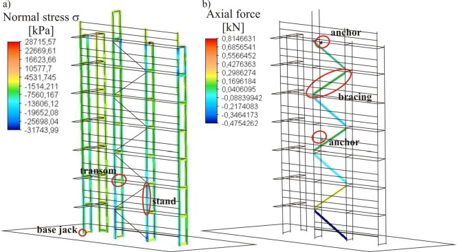
- Bending, Axial, and Shear stresses: The internal forces acting within scaffold members due to applied loads. These stresses must be within the material’s capacity to prevent failure.
Sophisticated engineering software can be employed for complex scaffold stability analysis, considering factors like material properties, connection details, and geometric configurations.
Key Design Principles
Several fundamental principles guide the structural design of scaffolds:
- Strength: All scaffold components must be strong enough to support the anticipated loads without exceeding their material yield strength.
- Stiffness: The scaffold must be sufficiently stiff to minimize deflection and maintain platform stability under load.
- Ductility: Scaffold materials should exhibit some degree of ductility to deform slightly under overload, providing a warning sign before failure.
- Stability: The scaffold must resist overturning and maintain its overall stability under varying load conditions.
- Safety: The design must prioritize worker safety by incorporating guardrails, toeboards, and other fall protection measures.
Sources and Citations
Chudly R. and Greeno R. (2005): Construction Technology (4th Ed.). Pearson Education Limited, England
Chudly R. and Greeno R. (2006): Advanced Construction Technology (4th Ed.). Pearson Education Limited, England

