When loads are applied on beams, they deflect. Deflection of beams is the downward movement a beam makes from its initial unloaded position to another deformed position when a load is applied to it. Since beams are usually treated as two-dimensional elements, the neutral axis of a beam is usually taken as the reference point for measuring the deflection of beams. The sag or curve that the deflected beam makes with the original neutral axis is called the elastic curve of the beam, while the angle of the elastic curve (in radians) is called the slope.
Calculation of deflection is very important in beams since it is a very important serviceability check in the design of structures. If deflection is excessive or beyond permissible limits, it may lead to cracks, damage to finishes, and misalignment of building services/fittings. Furthermore, the knowledge of deflections is the key in the analysis of statically indeterminate structures, since the equations of equilibrium are not sufficient for resolving such structures.
Relationship between Slope, Deflection, and Radius of Curvature
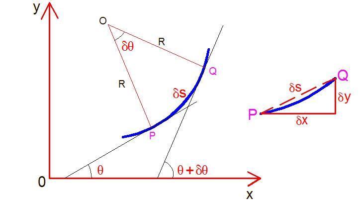
The figure above shows a small portion of a beam bent into an arc. Let us consider a small portion of the beam PQ
Let
δs = Length of the beam PQ
O = Centre of the arc unto which the beam has been bent
θ = The angle which the tangent at P makes with the x-axis
θ + δθ = The angle which the tangent at Q makes with the x-axis
From geometry;
δs = Rδθ
Therefore R = δs/δθ = dx/δθ (assuming δs = dx)
1/R = dθ/dx —- (1)
If the coordinates of points P and Q are x and y;
tan θ = dy/dx or θ = dy/dx (taking tan θ = θ since θ is very small).
Differentiatign the above equation with respect to x, we get;
dθ/dx = d2y/dx2
1/R = d2y/dx2 —- (2)
From the bending equation of beams, we know that;
M/I = E/R —– (3)
Substituing equation (2) into (3), we obtain;
M = – EI d2y/dx2 —- (4)
Equation (4) is known as the elastic curve equation and represents to the relationship between the bending moment and the displacements of the structure without considering shear deformation.
Methods of Assessing Deflection of Beams
The slope and deflection of beams can be calculated using the following methods;
(1) Double integration method
(2) Macaulays’ method
(3) Moment Area method
(4) Castigliano’s theorem
(5) Virtual work method (unit load method)
(6) Vereschagin’s rule (graphical method)
Solved Examples on Deflection of Beams
The deflection of cantilever and simply supported beams can be easily calculated using the double integration method or Vereschagin’s rule. Let us consider the above-named methods with the examples below;
Cantilever with a concentrated load at the free end

Let us consider the bending moment equation of a section x-x at a distance x from the fixed end A
Mx = -P(L – x)
From the elastic curve equation;
EI d2y/dx2 = P(L – x)
On integrating, we obtain;
EI dy/dx = P(Lx – x2/2) + C1
At A (fixed end), x = 0 and dy/dx = 0
Therefore C1 = 0
Hence;
EI dy/dx = P(Lx – x2/2) —- (a) is the equation for the slope
At x = L (free end, point B);
θB = EI dy/dx = P(L × L – L2/2) = P(L2 – L2/2) = PL2/2
Therefore;
θB = PL2/2EI
To get the deflection, let us integrate equation (a);
EIy = P(L·x2/2 – x3/6) + C2
At A (fixed end), x = 0 and y = 0;
Therefore, C2 = 0
EIy = P(L·x2/2 – x3/6) —- (b) is the equation for the deflection
At x = L (free end, point B);
yB = EI y = P(L·L2/2 – L3/6) = PL3/3
Therefore;
yB = PL3/3EI
This same problem can be solved by combining two different bending moment diagrams according to Vereschagin’s rule. The first bending moment diagram is produced by the externally applied load, while the second bending moment diagram is produced by a unit load applied at the point where the deflection is sought. In order to obtain the deflection at that point, the area of the first bending moment diagram is multiplied by the ordinate that its centroid makes with the second bending moment diagram.
This is based on the famous Mohr’s integral which is given by;
δ = 1/EI∫MṀ ds
For the problem above, the bending moment due to the externally applied load is given below;
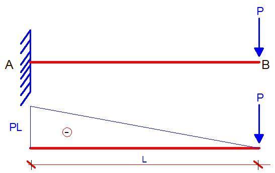
In order to obtain the deflection at point B, the external load P is replaced by a unit vertical load, and the bending moment diagram is plotted as shown below;
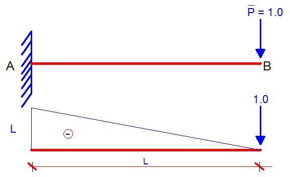
The deflection at point B is now obtained by combining the two bending moment diagrams according to Vereschagin’s rule.
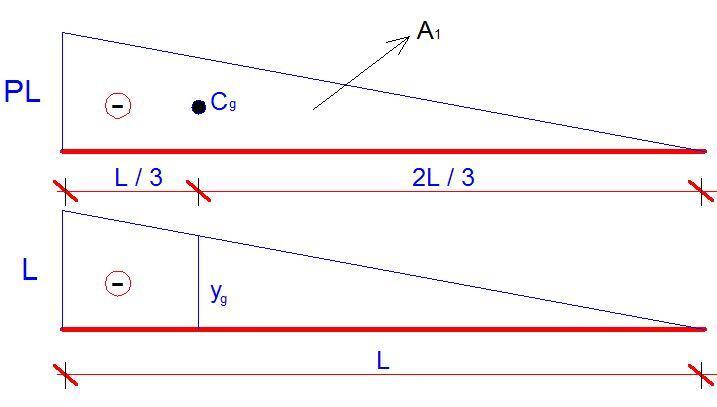
As we all know, the area of the main diagram is given by A1 = bh/2 = (PL × L)/2 = PL2/2. Since the shape is a triangle, the centroid will occur at L/3 from point A. If the location of the centroid is traced down to the second diagram, the ordinate it makes (yg) can easily be calculated using similar triangles as 2L/3.
Note: When forming the flexibility matrix of structures using force method of structural analysis, the value obtained from the multiplication of A1 and yg is known as the ‘influence coefficient‘.
Therefore;
A1 = PL2/2
yg = 2L/3
δB = A1yg/EI = (PL2/2) × (2L/3) = PL3/3EI (This answer is the same as the one obtained using the double integration method).
To calculate the slope at point B, the vertical unit force at point B is replaced with a unit rotation (a unit moment), and the bending moment diagram obtained is combined accordingly with the bending moment diagram due to the externally applied load.
However, you may not need to bother so much about calculating the area, centroid, and ordinates of every shape since standard tables are available for different kinds of bending moment diagram combinations. You can download a copy HERE. An excerpt from the publication is given in the Table below.
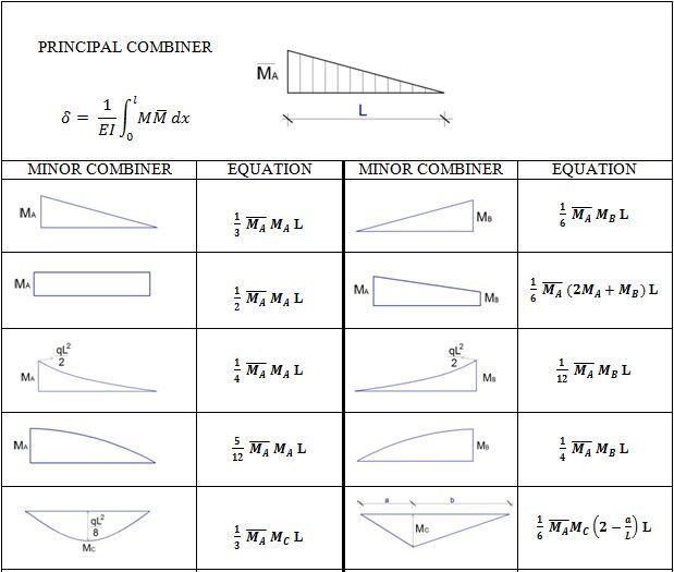
For instance, when a triangle is combined with a triangle, the influence coefficient is given by (1/3 × MA × ṀA × L).
Cantilever with a uniformly distributed load
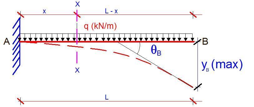
Let us consider the bending moment equation of a section X-X at a distance x from support A. The bending moment is given by;
Mx = -q(L – x)2/2
EI d2y/dx2 = q(L – x)2/2
On integrating;
EI dy/dx = -q(L – x)3/6 + C1
At x = 0, dy/dx = 0
Therefore, C1 = qL3/6
The general equation for slope is therefore given by;
EI dy/dx = -q(L – x)3/6 + qL3/6 —– (c)
At x = L (point B);
θB = qL3/6EI
To get the equation for deflection, we integrate equation (c);
EI y = q(L – x)4/24 + (qL3/6)x + C2
At x = 0, y = 0
Therefore, C2 = -qL4/24
The general deflection equation is therefore given by;
EI y = q(L – x)4/24 + (qL3/6)x – qL4/24 —– (d)
At x = L (point B);
yB = qL4/8EI
Using Vereschagin’s rule;
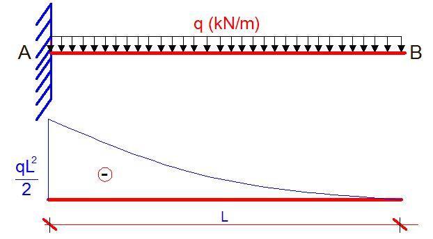
The external load q (kN/m) is replaced by a unit vertical load placed at point B, and the bending moment diagram is plotted as shown below;

The deflection at point B is now obtained by combining the two bending moment diagrams according to Vereschagin’s rule.
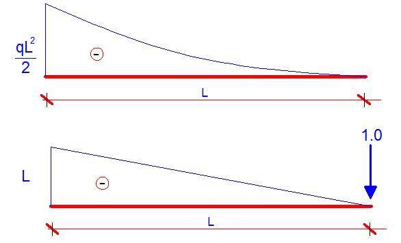
δB = (1/4 × MA × ṀA × L) = (1/4 × qL2/2 × L × L) = qL4/8EI
Simply supported beam with a concentrated load at the mid-span
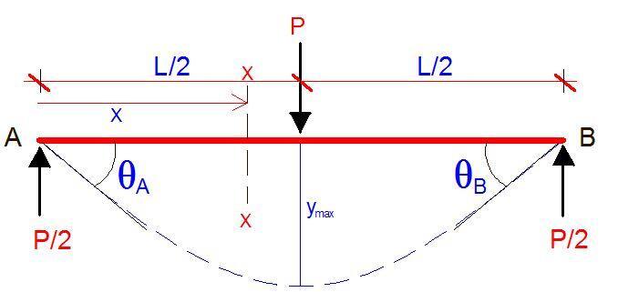
At a section X-X from support A, the bending moment equation is given by;
Mx = Px/2
EI d2y/dx2 = -Px/2
Integrating;
EI dy/dx = -Px2/4 + C1
At x = L/2, dy/dx = 0 (slope is zero at the point of maximum deflection);
Therefore C1 = PL2/16
The general equation for slope is therefore given by;
EI dy/dx = -Px2/4 + PL2/16 ——- (e)
At x = 0;
θA = PL2/16EI (radians)
Integrating equation (e), we obtain;
EI y = -Px3/12 + (PL2/16)x + C2
At x= 0, y = 0
Therefore, C2 = 0
The general equation for deflection is therefore given by;
EI y = -Px3/12 + (PL2/16)x ——- (f)
At x = L/2;
ymax = PL3/48EI
Using Vereschagin’s rule;
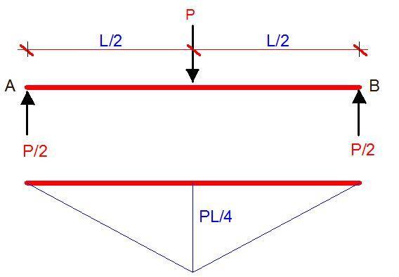
Let us replace the load P with a virtual unit load and plot the bending moment diagram;
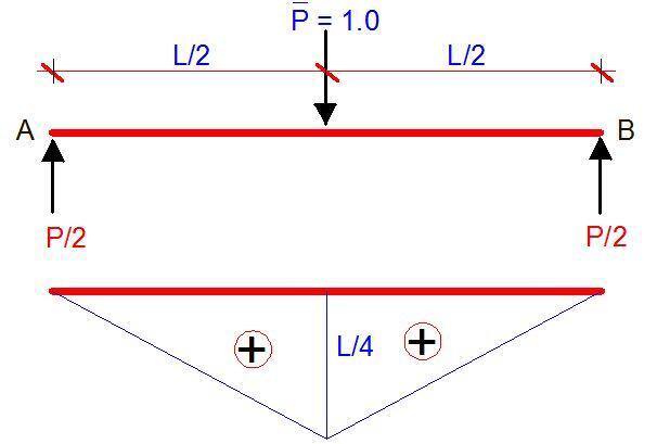
On the combination of the two diagrams;
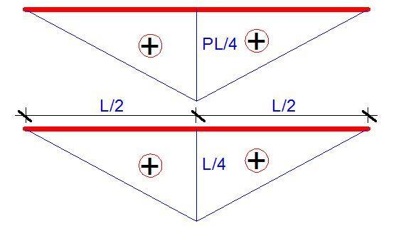
δmax = 2(1/3 × PL/4 × L/4 × L/2) = 2(PL3/96) = PL3/48EI
Simply supported beam with a uniformly distributed load
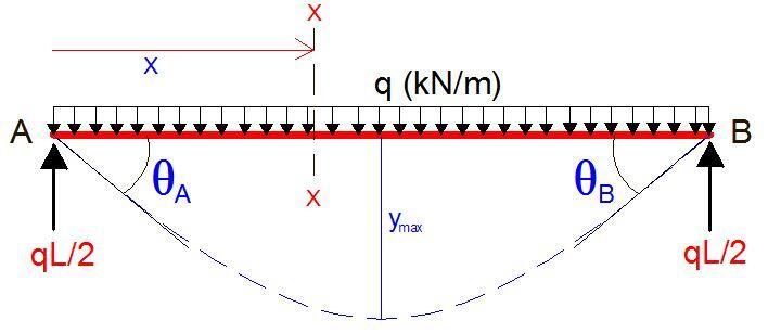
At a section X-X from support A, the bending moment equation is given by;
Mx = (qL/2)x – qx2/2
EI d2y/dx2 = -(qL/2)x + qx2/2
On integrating;
EI dy/dx= -qLx2/4 + qx3/6 + C1
At x = L/2; dy/dx = 0;
C1 = qL3/24
Therefore, the general slope equation is given by;
EI dy/dx= -qLx2/4 + qx3/6 + qL3/24 —– (g)
At x = 0;
θA = PL3/24EI (radians)
On integrating the equation for slope;
EI y= -qLx3/12 + qx4/24 + (qL3/24)x + C2
At x = 0, y= 0;
C2 = 0
Therefore the general deflection equation;
EI y= -qLx3/12 + qx4/24 + (qL3/24)x —– (h)
At x = L/2;
ymax = 5qL4/384EI
Using Vereschagin’s rule;
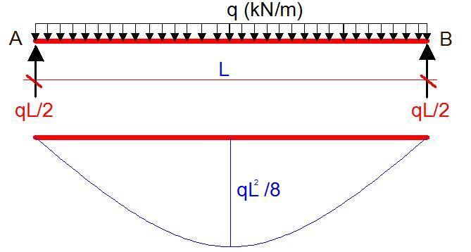
Let us replace the UDL with a virtual unit load and plot the bending moment diagram;

The diagram combination is now given by;
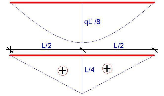
δmax = 2(5/12 × qL2/8 × L/4 × L/2) = 2(5qL4/768) = 5qL4/384EI


Nice
You have been of much help to many