EN 1991-1-7 discussed and gave guidance on accidental actions and their applications in the design calculations for bridge structures. It is obvious that there is a possibility of vehicles impacting on the substructure and/or superstructure of bridges. In order to reduce the negative effects in accidental actions, priority should also be given to reducing the risk of accidental impacts. Some risk reducing measures are;
(1) Preventing the accidental action from occurring or reducing the probability and/or magnitude of the action to a reasonable level.
(2) Protecting the structure against accidental actions (for example by using traffic bollards)
(3) Designing the structure in a such a way that neither the whole structure nor an important part of it will collapse if local failure should occur.
(4) Designing key elements of the structure with special care
(5) Applying prescriptive design and detailing rules which will lead to a robust structure.
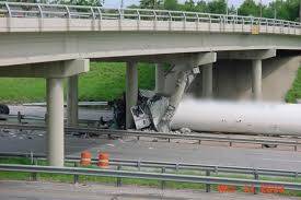
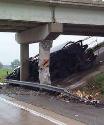
Traffic Impact on Bridge Piers
Impacts on the substructure of bridges (such as piers) by road vehicles are a relatively frequent occurrence and may have considerable consequences (see Figure 1 and 2). For soft impacts (when the impacting body consumes most of the available kinetic energy), the design values for the horizontal actions due to impact on vertical structural elements (e.g columns, walls) are shown in Table 1.
Table 1: Equivalent horizontal static action for traffic impact of bridge substructures (Vrounwenvelder and Diamantidis, 2010)

The forces Fdx and Fdy denote respectively the forces in the driving direction and perpendicular to it. There is no need to consider them simultaneously. The collision forces are supposed to act at 1.25 m above the level of the driving surface (0.5 m for cars). The force application area may be taken as 0.25 m (height) by 1.50 m (width) or the member width, whichever is the smallest.
Design Example
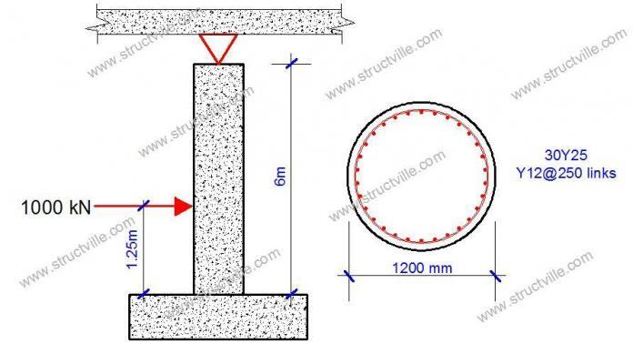
Consider a circular bridge pier with a diameter of 1200 mm. The height of the column is 6 m and is assumed to be hinged to the bridge deck and fixed to the foundation (pile cap) as shown in Figure 3. The main reinforcement consists of 30Y25 (Asprov = 12570 mm2) with a yield strength of 460 Mpa, and concrete strength of 40 Mpa. Let us check the column for truck vehicle collision under motorway conditions.
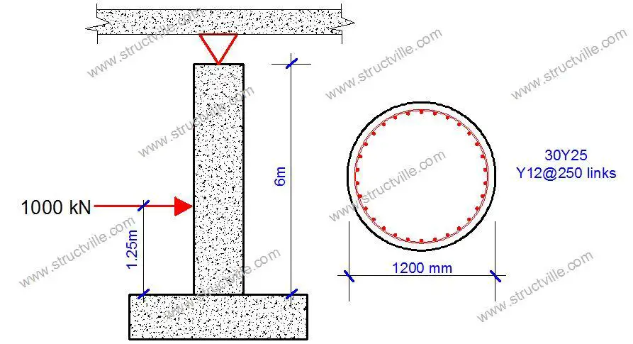
The simple structural idealisation of the system and the analysis result is shown in Figure 4. You can analyse the structure using any means at your disposal.
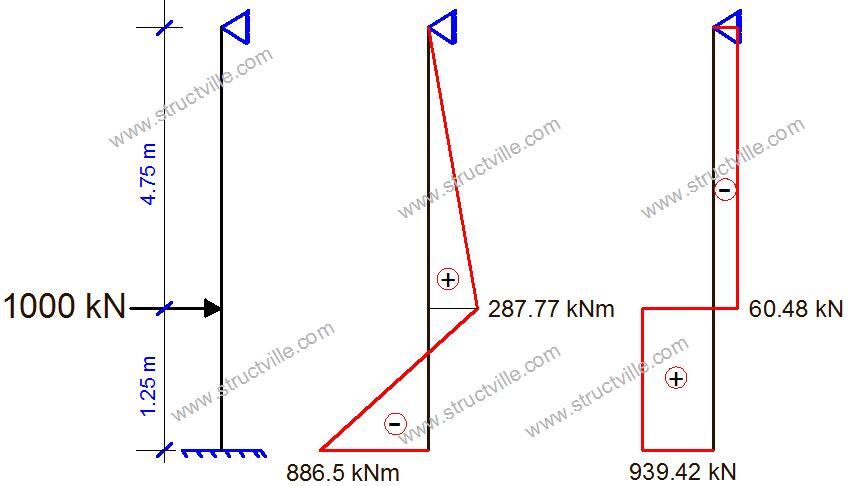
Note that other loads are not relevant in this case. The self weight of the bridge deck and traffic loads on the bridge will lead to normal force in the pier. Therefore, at the point of impact, the axial force will interact with the bending moment, but for this article, let us ignore the effect of the axial force and confine ourselves to the accidental action only. Note that this accidental action is not supposed to be factored.
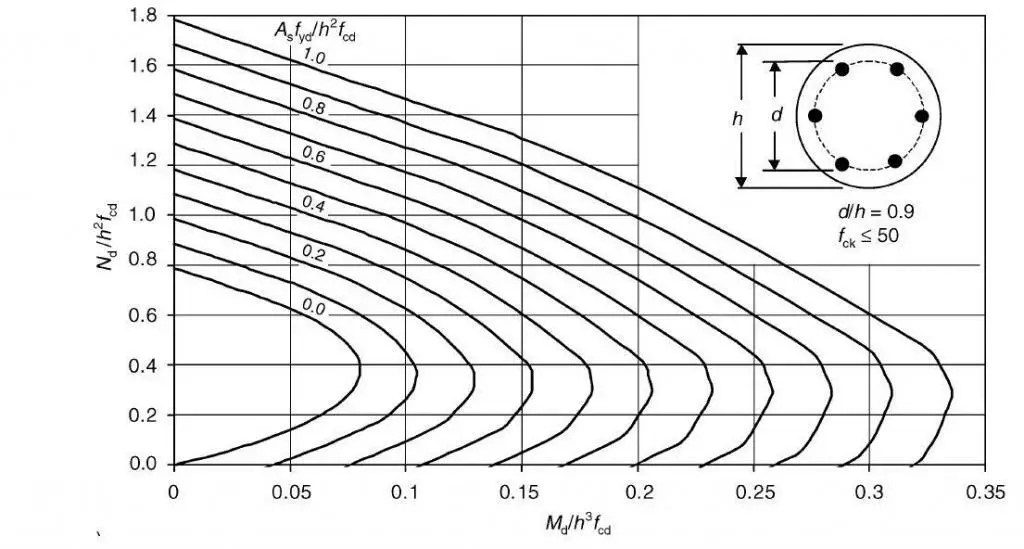
Therefore the simplified moment capacity of the section without considering axial force can be obtained from the interaction diagram (d/h = 0.9) given in Figure 5.
Design strength of reinforcement fyd = 0.87fyk = 0.87 x 460 = 400.2 MPa
Design strength of concrete in compression fcd = αccfck/γc = (0.85 x 40)/1.5 = 22.667 MPa
Asfyd/h2fcd = (12570 x 400.2)/(12002 x 22.667) = 0.154
MEd/h3fcd = (886.5 x 10⁶)/(12003 x 22.667) = 0.0226
At zero axial force (NEd/h2fcd = 0), Asfyd/h2fcd = 0.05 (Figure 4).
Therefore, the area of steel required to resist bending moment due to impact only;
As = (0.05 x 12002 x 22.667)/400.2 = 4078 mm2
A little consideration will show that this is less than the area of steel provided (Asprov = 12570 mm2). It is left for the designer to evaluate the axial force coming from the bridge deck to fully verify the adequacy of the reinforcement provided. The shear capacity of the section should also be checked.
References
Vrounwenvelder T., and Diamantidis D. (2010): ‘Accidental Actions’ in Guidebook 2 Design of Bridges (Pietro Croce Ed). Faculty of Engineering University of Pisa and Leonardo De Vinci Project.
αγ



This article is superb senior engineer.God bless u.
Very helpful and educative, just as other publications. The figures are not displaying. Thanks Engr. Keep it up
Thanks. It’s obviously a network issue… Refresh the page when you have better network.
Welldone engr, i would like to keep intouch with you sir
Really interesting… thanks
Well done Engr
That’s a very insightful analysis and it is extremely helpful. Keep up the good work. May god bless you
how do i get in touch with you?
ubani@structville.com
Thanks for this article, it’s very helpful.