A double-cell box culvert is a type of box culvert with two major openings separated by a reinforced concrete wall. It is a prevalent type of precast or cast-in-situ concrete structure employed for conveying stormwater, drainage channels, or even small streams beneath roadways or embankments.
The reason for the adoption of double or more-celled box culverts is to efficiently convey the design stormwater without having excessive span for the culvert. Furthermore, when the height of the embankment is low, or the natural width of the waterway is so wide, a multi-celled box culvert can come in handy.
A degree of structural efficiency is achieved by partitioning a single box culvert into multiple cells. This may become a more attractive and economical alternative once the span of a single box culvert exceeds 3m. The partition walls serve as intermediate supports and reduce the span of the culvert.

By so doing, the deflection and span bending moment on the top slab of the culvert are reduced. Furthermore, as a result of the additional constraints on the structure, there is a significant redistribution of stresses as vehicles of different sizes ply the top of the culvert.
Precast double-cell box culverts are favoured for their structural efficiency, hydraulic performance, and rapid installation compared to cast-in-place alternatives.

There are however some potential disadvantages of multi-celled culverts.
- Clogging: The space between the two culvert cells can act as a trap for debris and sediment, particularly in areas with high bed load or heavy vegetation. This accumulation can impede water flow and potentially lead to culvert blockage.
- Sedimentation in Widened Channels: When a natural channel is artificially widened to accommodate multiple culverts, the barrels positioned beyond the main flow path (outside the dominant channel) are more susceptible to excessive sediment deposition. This is because they may not experience the same level of water flow scouring that keeps the main channel clear.
- Effective Span of Multiple Barrel Culverts: When calculating the total flow capacity of multiple barrel culverts placed side-by-side, the spacing between the barrels can be included in the overall span or opening length. However, this is only valid if the spacing is less than half the opening length of the individual culvert barrels. Exceeding this limit would compromise the hydraulic efficiency of the system.
This technical article discusses the critical aspects of designing double-cell box culverts, covering material selection, loading, structural analysis, and hydraulic considerations.
Material Selection
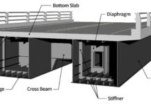
A typical double-cell box culvert will consist of the base slab, top slab, base/bottom slab, side walls, internal/partition wall, wing walls, aprons and headwalls. The box is typically constructed from precast concrete units, but they can also be constructed in situ. The box is placed on a well-prepared ground that has been blinded with concrete of specified grade and thickness.
The concrete should conform to BS EN 206-1 or relevant ASTM specifications, such as ASTM C33 for standard strength concrete or ASTM C476 for grey moving and paving concrete. The specified compressive strength will depend on the anticipated loads and burial depth of the culvert.
When designing for aggressive environments or freeze-thaw cycles, it may be necessary to incorporate additional considerations:
- Sulfate Resistance: For sulfate-rich soils, selecting concrete with Type II Portland cement or supplementary cementitious materials (SCMs) that enhance sulfate resistance becomes crucial.
- Freeze-Thaw Durability: Air-entrained concrete is recommended in regions susceptible to frequent freeze-thaw cycles. The entrained air voids provide space for the expansion of water during freezing, mitigating the risk of concrete cracking.
In specific situations, alternative materials like galvanized steel or high-density polyethylene (HDPE) pipes might be considered. However, these options are generally less common for double-cell box culverts due to limitations in span capabilities and live load capacity.
Hydraulic Design of Double-cell Box Culvert
Hydraulic analysis is very important to ensure the culvert has sufficient capacity to convey the anticipated flow rate without causing upstream flooding or excessive outlet velocities. Key factors to consider include:
- Design Flow Rate: The maximum water flow rate the culvert needs to accommodate. This is determined by hydrological studies considering factors like drainage area, rainfall intensity, and return period.
- Watercourse Slope: The natural gradient of the stream or channel flowing through the culvert.
- Manning’s Roughness Coefficient: A value representing the frictional resistance of the culvert material to water flow.
- Headwater and Tailwater Depths: The water depths upstream and downstream of the culvert, respectively. These depths influence the available energy head for flow through the culvert.
Hydraulic analysis software or Manning’s equation can be used to calculate the culvert’s hydraulic capacity and ensure it meets the design flow rate requirements. The software considers factors like culvert geometry, slope, and roughness coefficient to determine the flow velocity and water depth within the culvert.

Loading on Double Cell Culverts
The loading on double-cell box culverts is similar to the loading on single-cell box culverts. They are;
Permanent Loads
This category encompasses all static loads acting on the structure that remain constant over time. They can be further broken down into:
- Dead Loads: The self-weight of the structural components themselves such as the top slab, side walls, etc
- Superimposed Dead Loads: The weight of permanent, non-structural elements placed on the structure, such as earth fill, asphalt laying, sidewalks, utility lines, railings, and fixed partitions.
- Horizontal Earth Pressure: The lateral pressure exerted by surrounding soil masses against the structure’s buried components.
- Hydrostatic Pressure and Buoyancy: The pressure exerted by water acting on submerged portions of the structure. Buoyancy represents the upward force acting on the structure due to water displacement.
- Differential Settlement Effects: Uneven settlement of the foundation supporting the structure can induce additional stresses and require special design considerations.
Vertical Live Loads
These represent the dynamic vertical loads applied to the structure due to moving traffic or pedestrians. They can be further categorized:
- HA or HB Loads on the Carriageway: These represent the standardized design vehicle loads specified in design codes, such as the AASHTO (American Association of State Highway and Transportation Officials) specifications. In Eurocode, we talk about Load Model 1, Load Model 2 or Load Model 3.
- Footway and Cycle Track Loading: The weight of pedestrians and cyclists using designated walkways or cycle tracks on the structure.
- Accidental Wheel Loading: Loads resulting from an errant vehicle potentially encountering a curb or edge of the structure.
- Construction Traffic: Loads imposed by heavy equipment or vehicles used during construction or maintenance activities on the structure.

Horizontal Live Loads
These represent the dynamic horizontal forces acting on the structure:
- Live Load Surcharge: The additional horizontal pressure exerted by vehicles during construction, service, or maintenance on the buried walls of the culvert.
- Traction: The horizontal force generated by vehicle tyres against the structure’s surface, which can influence stability under braking or acceleration conditions.
- Temperature Effects: Thermal expansion and contraction of the structure’s materials due to temperature variations can induce horizontal forces.
- Parapet Collision: The impact force exerted by a vehicle colliding with the structure’s parapet wall.
- Accidental Skidding: The horizontal force resulting from a vehicle losing traction and skidding across the structure’s surface.
- Centrifugal Load: The outward horizontal force acting on a curved structure due to vehicle traffic negotiating the curve.
Load Combinations
The load combinations to be used in the design shall be as given in BD 37. Only combinations 1, 3 and 4 apply to this standard as follows:
(a) Combination 1
Permanent loads, Vertical live loads and Horizontal live load surcharge.
(b) Combination 3
Combination 1 plus temperature effects.
(c) Combination 4
Permanent loads and Horizontal live load surcharge plus one of the following:
i. Traction
ii. Accidental load due to skidding
iii. Centrifugal loads
iv. Loads due to collision with parapets and the associated vertical (primary) live loads in accordance with BD 37.
Structural Analysis
A thorough structural analysis is important to ensure the culvert can withstand anticipated dead and live loads. The structural analysis aims to determine the internal forces and displacements in the culvert such as bending moments, shear forces, and axial forces. Manual calculations can be adopted using methods such as;
(a) Force method
(b) Stiffness method
(c) Hardy cross moment distribution method
Commonly, structural analysis software utilising finite element analysis specifically designed for precast concrete culverts can be employed to efficiently evaluate these forces and determine the required dimensions and reinforcement for the culvert sections. The software considers various factors like span, burial depth, traffic loads, and soil properties to generate design outputs.
Design Example
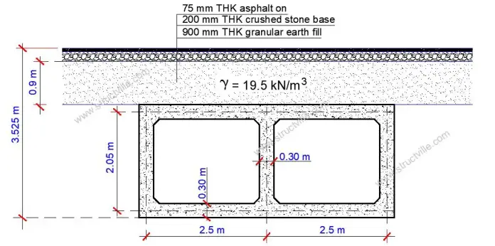
The geometry of a double-cell box culvert is shown below, with an earth cushion that is 900 mm thick from the pavement. The culvert is 9 m long, and it is expected to carry Load Model 1 traffic. The ground investigation report shows the foundation material to be cohesionless soil having an angle of internal friction (φ’) = 30° and a unit weight of 19 kN/m3. Design the culvert using the following materials data.
fck = 30 N/mm2
fyk = 500 N/mm2
All concrete cover = 50 mm
Unit weight of concrete = 25 kN/m3

Unit weight of backfill material (γ) = 19.5 kN/m3.
Angle of internal friction of backfill φ’ = 30°
Earth fill over the culvert = 900 mm thick (unit weight = 19.5 kN/m3)
Road stone base = 200 mm thick (unit weight = 20 kN/m3)
Asphalt paving = 75 mm thick (unit weight = 23 kN/m3)
Loading
Consider loading on a 1 m strip of the double-cell box culvert.
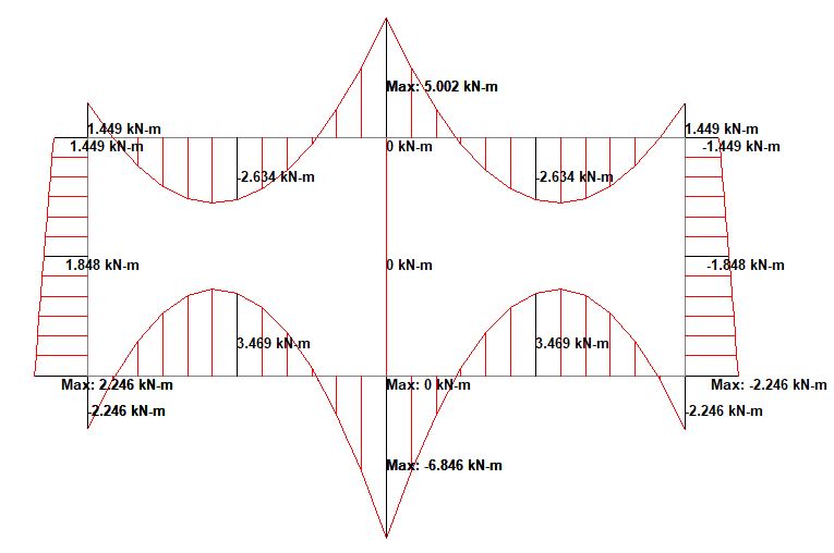
(i) Self Weight
Wall thickness = 300 mm
Top and bottom slab thickness = 300 mm
Unit weight of concrete (γ) = 25 kN/m3
Self-weight of top slab = (25 × 0.30) = 7.5 kN/m2
Self-weight of bottom slab = (25 × 0.30) = 7.5 kN/m2
Self-weight of walls = 3(25 × 0.30 × 1.75) = 39.375 kN/m
Weight of culvert per metre run = 2(7.5 × 5.3) + 39.375 = 118.875 kN/m
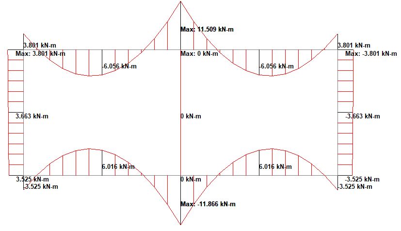
(ii) Earth Fill Over Culvert
Weight of earth fill per metre run = (19.5 × 0.9) = 17.55 kN/m
(iii) Road Construction
Weight of stone base = 20 × 0.2 = 4.0 kN/m
Weight of asphalt wearing course = 23 × 0.075 = 1.725 kN/m
(iv) Vertical Traffic Loading
According to clause 10.2.1 of PD 6694-1:2011, a buried concrete structure with a depth cover Hc less than 0.6 m should be treated as a normal bridge structure and designed for traffic specified in BS EN 1991-2. When the cover exceeds 0.6m, the vertical traffic action may be considered as dispersed through the fill at an angle of 30 degrees to the vertical.

When the dispersal zone of more than two wheels overlaps, the local pressure may be taken as the pressure of the most heavily loaded strip. In the figure below, PQ is the most heavily loaded segment. The load on the strip can be taken as bW1/L1 + aW2/L2. Where W1 is the load of the larger wheel and a is the overlap length. For metre strip designs, b should be taken as 1m.


Number of notional lanes = n1 = Int(w/3) = Int(9/3) = 3
Notional Lane Width = 3.0 m
Width of remaining area = 9 – (3 × 3.0) = 0
UDL in Lane 1 = αq1q1k = 0.61 × 9 = 5.5 kN/m2
UDL in Lane 2 = αq2q2k = 2.2 × 2.5 = 5.5 kN/m2
UDL in Lane 3 = αq3q3k = 2.2 × 2.5 = 5.5 kN/m2
TS in Lane 1 = Q1k = 300 kN
TS in Lane 2 = Q2k = 200 kN
TS in Lane 3 = Q3k = 100 kN
Contact patch area = 400 × 400mm
Depth of wheel load dispersal to the top of the culvert = 900 mm + 200mm + 75mm = 1175 mm
Dispersed area on top of box = 400 + (2 × 1175 × tan30°) = 1757 × 1757 mm

Load Model1 placement on the double-cell culvert
Maximum transverse load on strip = bW1/L1 + aW2/L2 = [(1 × 150)/1.757] + [(0.757 × 100)/1.757] = 85.37 + 43.084 = 128.45 kN/m2
Check also; 150/1.379 = 108.77 kN/m
Therefore, the overlap zone is the most critical.
Longitudinal Dispersal:
Dispersal zone width for each axle = 1.757m
Patch load for each axle = 128.45 / 1.757 = 73.1 kN/m
Load Model 2
Wheel load = 200 kN
Contact patch area = 400 × 400mm
Wheel spacing on axle = 2.0m ∴ dispersal zones do not overlap
Dispersed area on top of box = 400 + (2 × 1175 × tan30°) = 1757 × 1757 mm
Patch load for each wheel = 200 / 1.7572 = 64.78 kN/m
(v) Horizontal Surcharge Model for LM1
According to Table 6 of PD 6694-1:2011, the traffic surcharge for abutments and other buried structures may be given by a full UDL of 20Kd (kN/m2) and a horizontal line load F = 330Kd applied at the top of the structure for normal traffic category. Where Kd = Ka or K0.
For buried structures with a fill of less than 2m, a reduction factor (1 – Hc / 2)2 should be applied to the horizontal line load. Horizontal line load can be ignored when the depth of the fill exceeds 2m.
(1 – Hc / 2)2 = (1 – 1.175/2)2 = 0.17
Two line loads are applied so for a 3m lane width the load on a 1m wide strip = 0.17 × 330Kd = 56.1Kd kN.
Ka or K0 are obtained from the appropriate load case Table in Annex B.
UDL for LM1 and LM2 = 20Kd = 0.5 × 20 = 10 kN/m2
Horizontal line load = = 56.1Kd = 0.5 × 56.1 = 28 kN/m

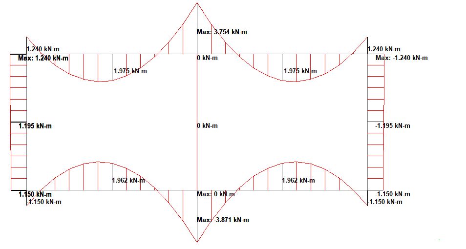
Earth Pressure on Box Walls Analysis
The lateral earth pressure acting on the sidewalls originates from two primary sources:
Backfill Pressure: This pressure originates from the soil mass retained between the foundation level and the top-of-roof level. It is typically modelled as a trapezoidal load distribution.
Earth pressure coefficient at rest K0 = 1 – sinφ = 1 – sin30 = 0.5. However, according to Annex B of PD 6694-1, Kmax should be taken as 0.6 for SLS and 0.72 for ULS.
Pressure at the bottom of wall = K0γZ = 0.6 × 19.5 × 3.25 = 38 kN/m2
Pressure at the top of wall = K0γZ = 0.6 × 19.5 × 0.9 = 10.53 kN/m2
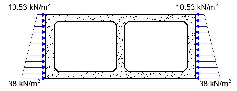
Surcharge Pressure: This pressure arises from any additional load situated above the roof level, such as soil overburden or a constructed carriageway. It is commonly modelled as a uniformly distributed load (UDL).
Surcharge due to stone base = 20 × 0.2 = 4.0 kN/m2
Surcharge due to asphalt wearing course = 23 × 0.075 = 1.725 kN/m2
Total permanent load surcharge = 4 + 1.725 = 5.725 kN/m2
Horizontal surcharge load = 0.5 × 5.725 = 2.86 kN/m2

Structural Modelling
A two-celled box culvert can be analytically modelled in two ways: as a simplified 2D frame element model or a more detailed 3D space frame model with a unit length. Regardless of the chosen method, the supporting foundation can be simulated using elastic soil springs (for a 3D space frame) or as fixed supports using a 2D frame model. Staad Pro software can then be employed to establish the finite element model.
The 3D space frame model discretizes the culvert shell using plate elements. Additional dummy beam elements can be incorporated where necessary for enhanced accuracy. Dead and live loads are applied within the model, and the resulting stresses and deformations are analyzed through finite element analysis.
Analysis Results
(1) Self-weight
(2) Earth fill
(3) Road Construction
(4) Earth pressure on wall
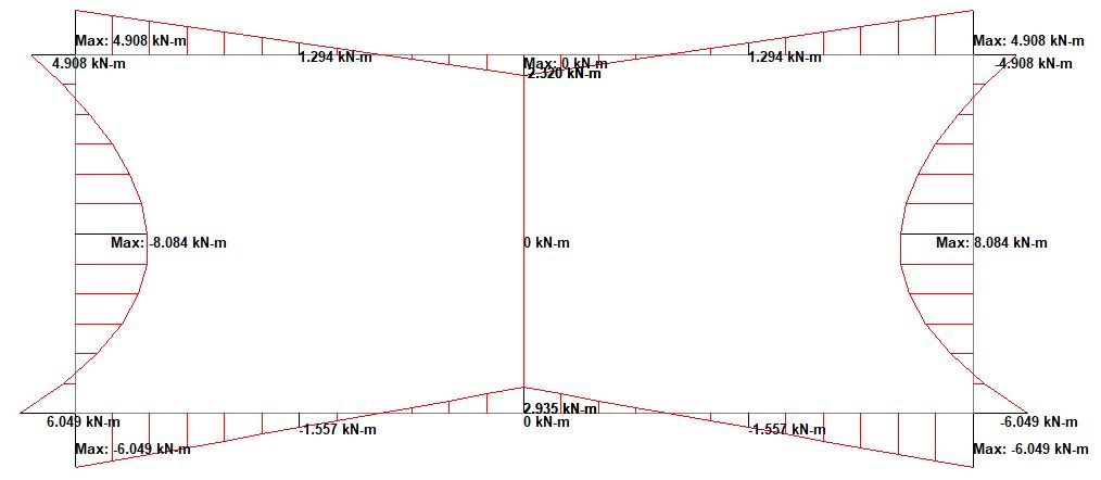
(5) Vertical Traffic Load
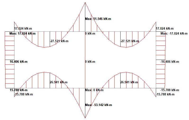
(6) Traffic Surcharge
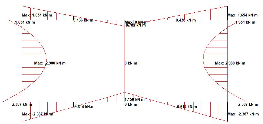
Partial Factors for Ultimate Limit State (Combination 1)
(a) Self-weight = 1.35
(b) Earth fill = 1.2 × 1.15 = 1.38
(c) Road Construction = 1.2 × 1.15 × 1.55 = 2.14
(d) Earth pressure on the wall (including surcharge) = 1.35 × 0.72 / 0.6 = 1.62
(e) Vertical traffic load = 1.35
(f) Live load surcharge = 1.35 × 0.5 / 0.5 = 1.35
When all these factors are applied, the internal forces at the ultimate limit state are shown below;
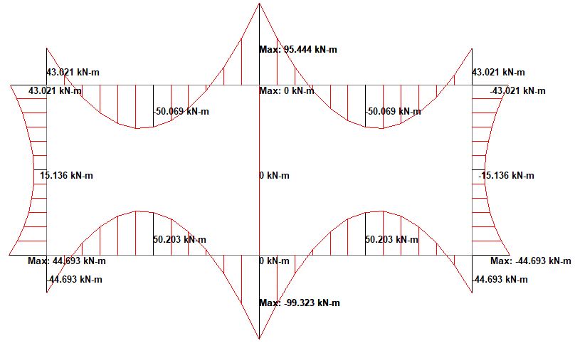
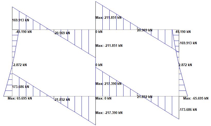
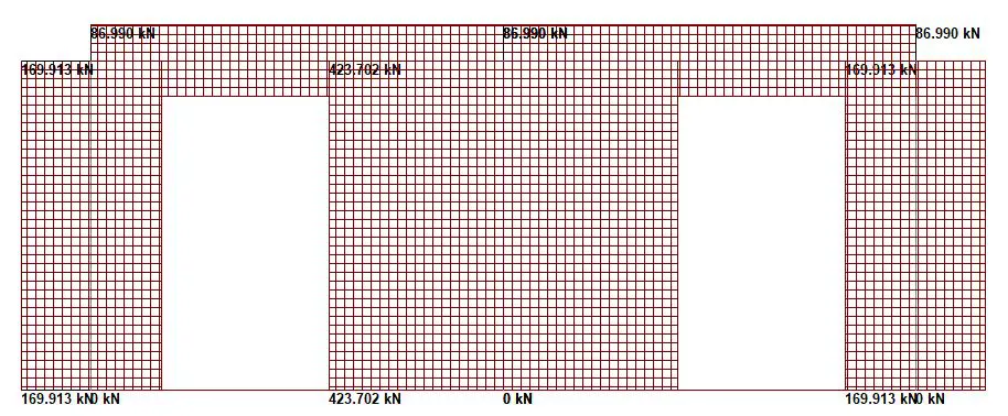
Structural Design
Top Slab and Bottom Slab
Reinforcement design at midspan of span 1 (cl.6.1)
Length of span = 2500 mm
Design bending moment; MEd = 50.2 kNm/m
Effective depth to tension reinforcement; d = h – cnom – φ/2 = 244.0 mm
K = MEd / (bd2fck) = 0.0281
K < K’ – Compression reinforcement is not required
Lever arm; z = min[0.95d, 0.5(1 + √(1 – 3.53K))]
z = 231.8 mm
As,req = MEd / (fydz) = 497 mm2/m
As,min = max(0.26(fctm/fyk), 0.0013)bd = 368 mm2/m
Asreq = max(Asreq, As,min) = 497 mm2/m
Reinforcement provided; H12@175 mm centres;
Area provided; Asp1 = 646 mm2/m
Reinforcement Design at Support
Design bending moment; MEd = 99.3 kNm/m
Effective depth to tension reinforcement; d = h – cnom – φ/2 = 242.0 mm
K = MEd / (bd2fck) = 0.056
K < K’ – Compression reinforcement is not required
Lever arm; z = min[0.95d, 0.5(1 + √(1 – 3.53k))]
z = 229.9 mm
As,req = MEd / (fydz) = 993 mm2/m
As,min = max(0.26(fctm/fyk), 0.0013)bd = 364 mm2/m
Asreq = max(Asreq, As,min) = 993 mm2/m
Reinforcement provided; H16@150 mm centres;
Area provided; Asp1 = 1340 mm2/m
Check for combined bending and axial force
MEd = 99.3 kNm
NEd = 86.99 kN
MEd/bh2fcd = (99.3 × 10⁶)/(1000 × 3002 × 17) = 0.065
NEd/bhfcd = (86.99 × 10³)/(1000 × 300 × 17 ) = 0.017
Asfyd/bhfcd = As,min
As,min = 0.1NEd/0.87fyk = 25.55 mm2 < 0.002Ac = 0.002 × 1000 × 300 = 600 mm2
Check for Shear
Shear is considered at a distance d away from the support. As the critical sections (d from support) are close to points of contraflexure then tension can occur both on the inside and outside faces of the structure. The longitudinal tensile steel to resist shear should therefore be provided on both faces.
VEd at d from the face of the middle wall = 155.07 kN/m
VRd,c = [CRd,c.k.(100ρ1 fck)(1/3) + k1.σcp]b.d ≥ (Vmin + k1.σcp) b.d
CRd,c = 0.18/γc = 0.18/1.5 = 0.12
k = 1 + √(200/d) = 1 + √(200/242) = 1.9
Vmin = 0.035k(3/2) fck0.5
Vmin = 0.035 × (1.9)1.5 × 300.5 = 0.502 N/mm2
ρ1 = As/bd = 1340/(1000 × 242) = 0.005537 < 0.02
σcp = NEd/Ac < 0.2fcd (Where NEd is the axial force at the section, Ac = cross-sectional area of the concrete), fcd = design compressive strength of the concrete.)
Take NEd = 86.99 kN = 86990 N
Ac = 1000 × 300 = 300000 mm2
σcp = NEd/Ac = 86990 /300000 = 0.2899 N/mm2
fcd = 17 N/mm2
0.2 fcd = 0.2 × 17 = 3.4 > 0.43 ∴ OK
VRd,c = [0.12 × 1.9 × (100 × 0.005537 × 30)(1/3) + 0.15 × 0.2899] × 1000 × 242 = 151293 N = 151.293kN/m ≥ (0.502 + 0.04348) × 1000 × 242 = 122536 N = 122.536 kN/m
Since VRd,c (151.293 kN/m) < VEd (155.07 kN/m), shear reinforcement is required.
The thickness of the top slab can be increased or corner splays introduced to increase shear resistance.
Design of the exterior walls
Wall geometry
Thickness; h = 300 mm
Length; b = 1000 mm/m
Axial load and bending moments from frame analysis
Design axial load; NEd = 169.913 kN/m
Moment about minor axis at top; Mtop = 43.0 kNm/m
Moment about the minor axis at the bottom; Mbtm = 44.7 kNm/m
Effective length for buckling about minor axis; l0 = 2000 mm
Vertical reinforcement = H16@200 c/c each face (Asv = 1005 mm2/m each face)
Horizontal reinforcement = H12@200 c/c near each face
Frame analysis moments combined with moments due to imperfections (cl. 5.2 & 6.1(4))
Ecc. due to geometric imperfections; ei = l0 /400 = 5.0 mm
Minimum end moment about minor axis;
M01 = min(abs(Mtop), abs(Mbtm)) + eiNEd = 43.8 kNm/m
Maximum end moment about minor axis;
M02 = max(abs(Mtop), abs(Mbtm)) + eiNEd = 45.5 kNm/m
Design moment about the minor axis;
MEd = max(M02, NEd × max(h/30, 20 mm)) = 45.5 kNm/m
Position of neutral axis; z = 56.7 mm
Concrete compression force (3.1.7(3));
Fc = hfcdmin(max(lsbz, 0 mm) , h)b = 771.3 kN/m
Moment of resistance;
MRdc = Fc [h / 2 – (min(lsbz , h)) / 2] = 98.2 kNm/m
Force in tension face bars; Fs =-437.1 kN/m
Force in compression face bars; Fs’ = -164.9 kN/m
Resultant concrete/steel force; F = Fc + Fs + Fs’ = 169.2 kN/m
This is within half of one percent of the applied axial load therefore say OK
Moment of resistance of tension face bars;
MRds = Fs(d – h/2) = -35.0 kNm/m
Moment of resistance of compression face bars;
MRds’ = Fs’(h / 2 – d’) = -13.2 kNm/m
Combined Moment of resistance about minor axis;
MRd = MRdc + MRds’ – MRds = 120. kNm/m < 45.5 kNm/m. Okay
Calculation shows that the crack width due to SLS effects is 0.184mm which is okay.
Design of the Internal Wall
Wall Thickness; h = 300 mm
Length; b = 1000 mm/m
Stability about minor axis; Braced
Design axial load; NEd = 423.7 kN/m
Moment about minor axis at top; Mtop = 0.0 kNm/m
Moment about minor axis at bottom; Mbtm = 0.0 kNm/m
Vertical reinforcement = H16@200 c/c each face (Asv = 1005 mm2/m each face)
Horizontal reinforcement = H12@200 c/c near each face
Frame analysis moments combined with moments due to imperfections (cl. 5.2 & 6.1(4))
Ecc. due to geometric imperfections; ei = l0 /400 = 5.0 mm
Minimum end moment about minor axis;
M01 = min(abs(Mtop), abs(Mbtm)) + ei × NEd = 2.1 kNm/m
Maximum end moment about minor axis;
M02 = max(abs(Mtop), abs(Mbtm)) + ei × NEd = 2.1 kNm/m
Design moment about minor axis;
MEd = max(M02, NEd × max(h/30, 20 mm)) = 8.5 kNm/m
Moment of resistance;
MRdc = Fc [h / 2 – (min(lsbz , h)) / 2] = 111.1 kNm/m
Force in tension face bars; Fs = -437.1 kN/m
Force in compression face bars; Fs’ = -41.0 kN/m
Resultant concrete/steel force; F = Fc + Fs + Fs’ = 421.6 kN/m
This is within half of one percent of the applied axial load therefore say OK
Moment of resistance of tension face bars;
MRds = Fs(d – h / 2) = -35.0 kNm/m
Moment of resistance of compression face bars;
MRds’ = Fs’ (h / 2 – d’) = -3.3 kNm/m
Moment of resistance about minor axis;
MRd = MRdc + MRds’ – MRds = 142.8 kNm/m
PASS – The moment capacity exceeds the design bending moment.
Detailing

Design Considerations and Best Practices
- Selection of Culvert Size: For precast double-cell culverts, standard unit dimensions are available from manufacturers. For in-situ culverts, the standard dimension is established on-site through standard setting out procedure. The chosen size should provide sufficient hydraulic capacity while optimizing material utilization and construction costs.
- Joint Design: The joints between precast units are critical for maintaining watertight integrity and structural continuity. Common joint designs include tongue-and-groove, gasketted, or belled-end configurations for precast culverts. Water bars may be integrated for cast in-situ culverts The chosen joint detail should be compatible with the anticipated loads and ensure effective load transfer between units.
- Bedding and Backfill: The culvert must be properly bedded on a stable foundation material to distribute loads evenly and prevent settlement. Select granular backfill materials are typically used to surround the culvert and provide lateral support. The backfill material should be compacted according to design specifications to ensure adequate load transfer and minimize the risk of differential settlement.
- Headwalls and Wingwalls: Headwalls and wingwalls are often incorporated at the inlet and outlet ends of the culvert to provide erosion protection, guide flow, and retain the surrounding soil mass. These structures can be constructed from precast concrete units, cast-in-place concrete, or masonry materials.




Hello,
I’m Hussain a civil Engineer. I’m interested in design of civil works. Please keep me posted as much as it is possible for you.