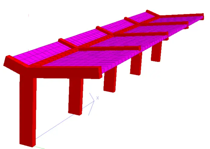
Cantilever monopitch roof pavilions offer an interesting combination of aesthetics and structural functionality. These structures feature a single, sloping roof supported on one side by columns or walls, extending outwards to create a covered space. They are commonly found in stadiums, assembly areas, carports, or institutional buildings.
The design of a reinforced concrete cantilever monopitch roof pavilion involves assessing the forces acting on the structure such as the self-weight, imposed loads, wind loads, etc, and providing adequate slab, beam, column, and foundation sections, with the proper amount of reinforcements to resist the most critical load combination.
This article discusses the considerations and the design example of a reinforced concrete (RC) monopitch roof pavilion, with the objective of equipping engineers and designers with the knowledge of the proper approach to carry out an effective design of such structures.
Structural Elements and Considerations
Typically, a cantilever monopitch pavilion consists of the roof slab, roof cantilever beams, vertical or inclined columns, and the foundation.
- Columns: The columns act as the primary vertical supports for the cantilevered roof. They must be designed to withstand the lateral bending moment and shear forces arising from the self-weight of the roof structure, imposed loads (wind, snow), and potential seismic activity. The column design should consider slenderness ratios, material strength (concrete and reinforcing steel), and support conditions.
- Roof beams: The roof beams typically receive load from the roof slab, and transfer it to the columns. The columns and the beams are constructed monolithically for good performance. The roof beams are essentially cantilever beam structures.
- Roof Slab: The roof slab, typically made of reinforced concrete, forms the main horizontal element spanning between the columns and cantilevering outwards. The slab thickness is determined by considering factors like dead load (self-weight), roof live load, wind uplift, and the desired span of the cantilever. The reinforcement layout within the slab must address both flexural and shear requirements.
- Foundations: The foundation system transfers the loads from the columns to the underlying soil. The choice of foundation type (pad footing, pile foundation) depends on the soil bearing capacity, structural loads, and site conditions.
Design Loads on Monopitch Roof Pavilion
- Dead Load: This encompasses the self-weight of all permanent elements, including the RC roof slab, columns, beams (if present), finishes, and any built-in fixtures. Accurate unit weight of materials is required for precise dead load calculations.
- Live Load: This accounts for the weight of occupants, furniture, and any anticipated equipment within the pavilion. Live load values are stipulated by building codes and depend on the intended use of the space.
- Wind Load: Wind exerts both uplift and lateral pressure on the roof structure. Wind load calculations consider the wind speed, building geometry, and surface roughness coefficients as defined by building codes.
- Snow Load: For regions experiencing snowfall, the roof must be designed to support the weight of accumulated snow. Snow load calculations depend on the geographical location, roof pitch, and importance factor specified in building codes.
- Seismic Load: In earthquake-prone areas, the structure must be designed to resist seismic forces. Seismic analysis involves considering the building’s response spectrum, site soil conditions, and the importance factor of the structure.
Material Selection and Properties
- Concrete: The choice of concrete mix strength is influenced by the desired load-carrying capacity and exposure conditions. Standard concrete mixes for structural applications typically range from 20 MPa to 40 MPa compressive strength.
- Reinforcing Steel: Steel reinforcement bars with appropriate yield strength and diameter are embedded within the concrete to enhance its tensile capacity. Common reinforcing steel grades include Fe 410 and Fe 500.
- Foundation Material: The foundation material selection depends on the soil properties and the required bearing capacity. Spread footings are often used for low-rise structures in good soil conditions, while pile foundations might be necessary for weaker soils or heavier loads.
Analysis and Design Methods
Several analytical methods can be employed for the design of a monopitch roof pavilion:
- Manual Calculations: For simpler structures, engineers can utilize engineering mechanics principles (theory of structures) and design codes to calculate member sizes and reinforcement requirements.
- Finite Element Analysis (FEA): This advanced computational method allows for a more detailed analysis of the structure’s behaviour under various loading conditions. FEA software can model complex geometries and material behaviour, providing valuable insights into stress distribution and potential weak points.
Design Example
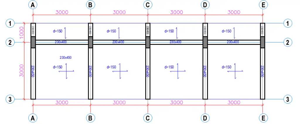
The layout of a simple cantilever monopitch roof pavilion is shown below. The roof is inclined at an angle of 7 degrees. The structure has the following dimensions:
Roof slab = 150 mm thick
Cantilever roof beams = 230 x 450 mm
Horizontal tie beams= 230 x 400mm
Columns = 230 x 600 mm

Wind Load Analysis
- Terrain category: = II
- Basic wind velocity: vb = 40 m/s
- Horizontal dimension of rectangular plan parallel to the wind direction: d = 4 m
- Horizontal dimension of rectangular plan perpendicular to the wind direction (crosswind dimension): b = 10 m
- Height of canopy from the ground up to the maximum roof level: h = 3.5 m
- Roof pitch angle: α = 7.125 °
- Degree of blockage under the canopy roof: φ = 0
- Orography factor at reference height ze: c0(ze) = 1
- Structural factor: cscd = 1

Net wind pressure on zone A wnet,A = (-2.191 or +1.673) kN/m2
Net wind pressure on zone B wnet,B = (-3.153 or +3.843) kN/m2
Net wind pressure on zone C wnet,C = (-3.325 or +2.463) kN/m2
Total wind force Fw = (-54.59 or +30.77) kN
The eccentricity of total wind force from windward edge e = 0.250d’ = 1.008 m
Structural Analysis
The structural analysis of the monopitch roof pavilion structure has been carried out using Staad Pro software. However, it is also very easy and possible to analyse the structure using manual calculation. In that case, the following steps can be followed.
(1) Determine the loading on the structure (roof slab).
(2) Determine the bending moment and shear forces on the slab due to the ultimate load, and design the slab. The slab can be designed as a two-way slab, taking into account the angle of inclination of the slab.
(3) Transfer the slab load to the beams using the yield line method.
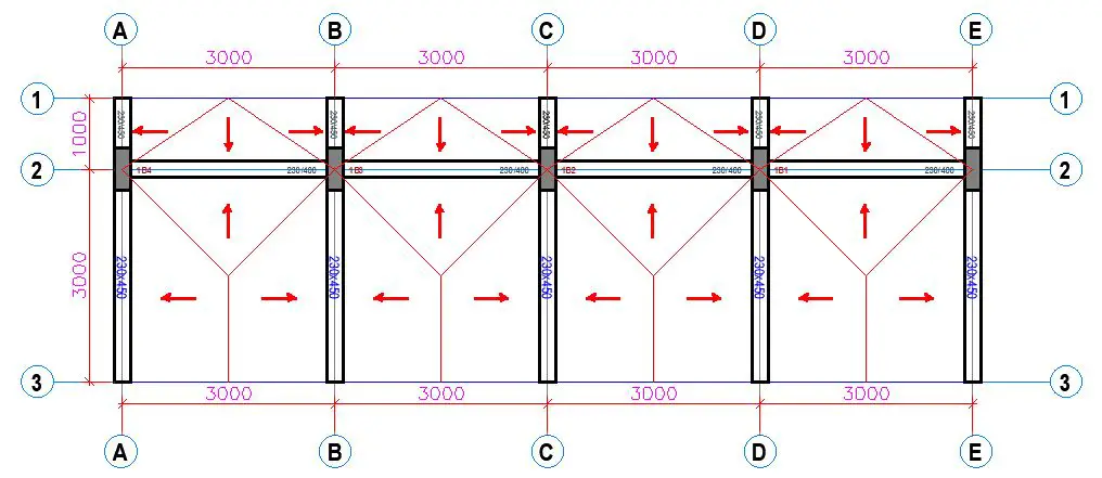
(4) Analyse the beams and columns as a framed cantilever structure using the load obtained from step 3, taking into account the self-weight of the beams and columns. The analysis should yield the critical bending moments, shears, and axial forces.
(5) Design the beams and columns by providing adequate sections and reinforcements to satisfy ultimate and serviceability limit state requirements.
(6) Design the foundation using the column reactions.
Design of the Slab


We intend to provide a similar reinforcement layout in both directions. Therefore, all sagging areas will have the same reinforcement layout, while all hogging areas will have the same reinforcement layout.
Design of the sagging areas
Design bending moment; MEd = 7.56 kNm/m
The effective depth of tension reinforcement; d = 119 mm
K = M / (bd2fck) = 0.0213
K’ = 0.207
K’ > K – No compression reinforcement is required
Lever arm; z = min(0.5d[1 + (1 – 3.53K)0.5], 0.95d) = 113.05 mm
Area of tension reinforcement required;
As,req = M/(fydz) = 154 mm2/m
The minimum area of reinforcement – exp.9.1N;
As,min = max(0.26fctm / fyk, 0.0013)bd = 155 mm2
Maximum allowable reinforcement spacing = 300 mm (Table 7.3N)
Tension reinforcement provided; H12@250 c/c Bottom (As,prov = 452 mm2/m)
Design of the hogging areas
Design bending moment; MEd = 25.81 kNm/m
The effective depth of tension reinforcement; d = 119 mm
K = M / (bd2fck) = 0.0729
K’ = 0.208
K’ > K – No compression reinforcement is required
Lever arm; z = min(0.5d[1 + (1 – 3.53K)0.5], 0.95d) = 110.67 mm
Area of tension reinforcement required;
As,req = M/(fydz) = 536 mm2/m
The minimum area of reinforcement – exp.9.1N;
As,min = max(0.26fctm / fyk, 0.0013)bd = 155 mm2
Maximum allowable reinforcement spacing = 300 mm (Table 7.3N)
Tension reinforcement provided; H12@150 c/c Top (As,prov = 735 mm2/m)
Design of the beams

Section details
Section width; b = 230 mm
Section depth; h = 450 mm
Maximum available flange width; bf = 1250 mm
Flange depth; hf = 150 mm
Concrete cover = 35 mm
Characteristic yield strength of reinforcement; fyk = 500 N/mm2
Characteristic compressive cylinder strength; fck = 25 N/mm2
Flexural Design of the Cantilever Section
Design bending moment; MEd = 123.4 kNm
The effective depth of tension reinforcement; d = 397 mm
K = M / (bd2fck) = 0.136
K’ = 0.207
K’ > K – No compression reinforcement is required
Lever arm; z = min(0.5d[1 + (1 – 2K / (hacc / gC))0.5], 0.95d) = 342 mm
Depth of neutral axis; x = 2(d – z) / l = 139 mm
Area of tension reinforcement required;
As,req = M/(fydz) = 831 mm2
Tension reinforcement provided; 3H20 mm (As,prov = 942 mm2)
The minimum area of reinforcement – exp.9.1N;
As,min = max(0.26fctm / fyk, 0.0013)bd = 122 mm2
Maximum area of reinforcement – cl.9.2.1.1(3);
As,max = 0.04bh = 4140 mm2
Deflection control
Reference reinforcement ratio; ρm0 = (fck )0.5 / 1000 = 0.005
Required tension reinforcement ratio; ρm = As,req / (beff × d) = 0.002093
ρm0/ρm = 0.005/0.002093 = 2.3886
Required compression reinforcement ratio; ρ’m = As2,req / (beff × d) = 0.00000
Structural system factor – Table 7.4N; Kb = 0.4
Basic allowable span to depth ratio ; span_to_depthbasic = Kb × [11 + 1.5 × (fck)0.5 × ρm0 / ρm + 3.2 × (fck)0.5 × (ρm0/ρm – 1)1.5] = 0.4 × [11 + 1.5 × (25)0.5 × 2.3886 + 3.2 × (fck)0.5 × (2.3886 – 1)1.5] = 0.4(11 + 17.9 + 26.18) = 22.032
Reinforcement factor – exp.7.17; Ks = min(As,prov / As,req × 500 N/mm2 / fyk, 1.5) = 1.5
Flange width factor; F1 = if(beff/b > 3, 0.8, 1) = 0.800
Long span supporting brittle partition factor; F2 = 1 = 1.000
Allowable span to depth ratio; span_to_depthallow = min(span_to_depthbasic × Ks × F1 × F2, 40 × Kb) = 16.000
Actual span to depth ratio = L / d = 3140/397 = 7.909
PASS – Actual span-to-depth ratio is within the allowable limit
Shear Design
The angle of comp. shear strut for maximum shear; θmax = 45 deg
Strength reduction factor – cl.6.2.3(3); v1 = 0.6 × (1 – fck / 250) = 0.540
Compression chord coefficient – cl.6.2.3(3); αcw = 1.00
The minimum area of shear reinforcement – exp.9.5N;
Asv,min = 0.08 N/mm2 × b × (fck )0.5 / fyk = 184 mm2/m
Design shear force at support ; VEd,max = 90 kN
Min lever arm in shear zone; z = 342mm
Maximum design shear resistance – exp.6.9; VRd,max = αcw × b × z × v1 × fcwd / (cot(θmax) + tan(θmax)) = 354 kN
PASS – Design shear force at support is less than the maximum design shear resistance
VEd = 90.6 kN
Design shear stress; vEd = VEd / (b × z) = 1.150 N/mm2
Angle of concrete compression strut – cl.6.2.3; θ = min(max(0.5 × Asin(min(2 × vEd / (αcw × fcwd × v1),1)), 21.8 deg), 45deg) = 21.8 deg
Area of shear reinforcement required – exp.6.8; Asv,des = vEd × b / (fyd × cot(θ)) = 243 mm2/m
Area of shear reinforcement required; Asv,req = max(Asv,min, Asv,des) = 243 mm2/m
Shear reinforcement provided; 2 × 8 legs @ 250 c/c
Area of shear reinforcement provided; Asv,prov = 402 mm2/m
PASS – The area of shear reinforcement provided exceeds the minimum required
Maximum longitudinal spacing – exp.9.6N; svl,max = 0.75 × d = 298 mm
PASS – The longitudinal spacing of the shear reinforcement provided is less than the maximum
Column Design


In accordance with EN1992-1-1:2004 incorporating Corrigendum January 2008 and the UK national annex
| Description | Unit | Provided | Required | Utilisation | Result |
| Moment capacity (y) | kNm | 243.09 | 174.86 | 0.72 | PASS |
| Moment capacity (z) | kNm | 76.75 | 14.54 | 0.19 | PASS |
| Biaxial bending utilisation | 0.91 | PASS |
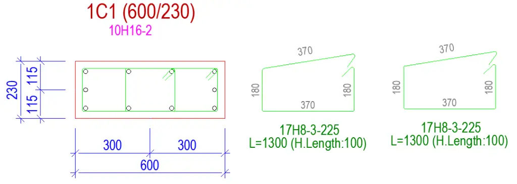
Column geometry
h= 600 mm;
b = 230 mm
Stability in the z direction; Unbraced
Stability in the y direction; Unbraced
Concrete and reinforcement details
Cylinder strength of concrete; fck = 25 MPa;
Nominal cover to links; cnom = 35 mm;
Longitudinal bar diameter; φ = 16 mm
Link diameter; φv = 10 mm;
Total no. of longitudinal bars; N = 10
No.bars per face parallel y-axis; Ny = 3
No.bars per face parallel z-axis; Nz = 4
Area of longitudinal reinforcement As = 2011 mm2;
Axial load and bending moments from frame analysis
Design axial load; NEd = 221.0 kN
Moment about y-axis at the top; Mtopy = 173.2 kNm;
Moment about y-axis at the bottom; Mbtmy = 131.5 kNm
Moment about z-axis at the top; Mtopz = 9.0 kNm
Moment about z-axis at bottom; Mbtmz = -9.0 kNm
Eff length for buckling about y; l0y = 3000 mm
Eff length buckling about z; l0z = 3000 mm
Column slenderness
Slend. ratio buckling abt y; ly = 17.3
Slend. ratio buckling abt z; lz = 45.2
Slend. limit about y; llimy = 40.1
Slend. limit about z; llimz = 40.1
Design bending moments
Design moment about y axis; MEdy = 174.9 kNm;
Design moment about z axis; MEdz = 14.5 kNm
Moment of resistances
Moment of resistance about y-axis; MRdy = 243.1 kNm;
Moment of resistance about z-axis; MRdz = 76.8 kNm
PASS – The moment capacity about the y-axis exceeds the design bending moment
PASS – The moment capacity about the z-axis exceeds the design bending moment
Biaxial Bending Check
Exponent a = 1.00
Biaxial bending utilisation;
UF = (MEdy / MRdy)a + (MEdz / MRdz)a = 0.909
PASS – The biaxial bending capacity is adequate
Foundation Design
It is desired to support the structure using separate pad bases. The design parameters are provided below;
Total depth of foundation = 1300 mm
Length of foundation; Lx = 1750 mm
Width of foundation; Ly = 1400 mm
Foundation area; A = Lx Ly = 2.450 m2
Trial thickness of foundation; h = 500 mm
Depth of soil over foundation; hsoil = 800 mm
Level of water; hwater = 0 mm
Density of water; γwater = 9.8 kN/m3
Density of concrete; γconc = 25.0 kN/m3
Soil properties
Density of soil; γsoil = 18.0 kN/m3
Characteristic cohesion; c’k = 12 kN/m2
Characteristic effective shear resistance angle; φ’k = 25 deg
Characteristic friction angle; δk = 20 deg
Foundation loads
Self weight; Fswt = h × γconc = 12.5 kN/m2
Soil weight; Fsoil = hsoil × γsoil = 14.4 kN/m2
Selected Characteristic Column loads
Permanent horizontal load in x; FGx1 = 2.2 kN
Permanent horizontal load in y; FGy1 = 8.6 kN
Permanent vertical load in z; FGz1 = 113.4 kN
Variable horizontal load in x; FQx1 = 1.4 kN
Variable horizontal load in y; FQy1 = 6.0 kN
Variable vertical load in z; FQz1 = 58.9 kN
Permanent moment in x; MGx1 = 77.3 kNm
Permanent moment in y; MGy1 = 2.2 kNm
Variable moment in x; MQx1 = 48.1 kNm
Variable moment in y; MQy1 = 1.4 kNm
Design Approach 1 – Combination 1
The foundation is biaxially loaded.
Forces on foundation
Factored force in x-axis = 5.0 kN
Factored force in y-axis = 20.6 kN
Factored force in z-axis = 330.4 kN
Moments on foundation
Moment in x-axis = 468.0 kNm
Moment in y-axis = 246.6 kNm
Eccentricity of base reaction in x-axis;
ex = Mdx / Fdz – Lx / 2 = 541 mm
The eccentricity of base reaction in y-axis;
ey = Mdy / Fdz – Ly / 2 = 46 mm
The effective area of base
Effective length; L’x = Lx – 2ex = 667 mm
Effective width; L’y = Ly – 2ey = 1307 mm
Effective area; A’ = L’x × L’y = 0.872 m2
Design base pressure;
fdz = Fdz / A’ = 378.9 kN/m2
Ultimate bearing capacity;
nf = c’dNcscic + q’Nqsqiq + 0.5γsoilL’xNγsγiγ = 598.9 kN/m2
PASS – Ultimate bearing capacity exceeds design base pressure
For Design Approach 1 – Combination 2
Design base pressure;
fdz = Fdz / A’ = 305.3 kN/m2
Ultimate bearing capacity;
nf = c’dNcscic + q’Nqsqiq + 0.5γsoilL’xNγsγiγ = 346.3 kN/m2
PASS – Ultimate bearing capacity exceeds design base pressure
Structural Design of the Footing
fck = 25 N/mm2
fyk = 500 N/mm2
Concrete cover = 50 mm
Flexural Design
Design bending moment;
MEd.x.max = 108.3 kNm
Effective depth d = 444 mm
K = 0.016
Lever arm z = 422 mm
Area of tension reinforcement required;
As,req= MEd / (fydz) = 591 mm2
Tension reinforcement provided;
10 No.12 dia. bars bottom (140 c/c) As,prov = 1131 mm2
Minimum area of reinforcement (exp.9.1N);
As.min = max(0.26fctm / fyk, 0.0013)Lyd = 829 mm2
Rectangular section in shear (Section 6.2)
Design shear force; VEd = 119.2 kN
CRd,c = 0.18/γC = 0.120
k = min(1 + √(200 mm / d), 2) = 1.680
Longitudinal reinforcement ratio;
ρl = min(As,prov / (Lyd), 0.02) = 0.002
vmin = 0.035k3/2fck0.5 = 0.381 N/mm2
Design shear resistance (exp.6.2a & 6.2b);
VRd.c = max(CRd.ck(100ρlfck)1/3, vmin)Lyd
VRd.c = 230.6 kN
PASS – Design shear resistance exceeds design shear force
Punching Shear
Design punching shear resistance (exp.6.47); vRd.c = 0.380 N/mm2
Design punching shear resistance at 1d (exp. 6.50); vRd.c1 = (2d/d)vRd.c = 0.759 N/mm2
Punching shear perimeter at column face
Punching shear perimeter; u0 = 1660 mm
Area within punching shear perimeter; A0 = 0.138 m2
Maximum punching shear force; VEd.max = 238.4 kN
Punching shear stress factor (fig 6.21N); β = 1.500
Maximum punching shear stress (exp 6.38);
vEd.max = βVEd.max / (u0d) = 0.492 N/mm2
PASS – Maximum punching shear resistance exceeds maximum punching shear stress
Punching shear perimeter at 1d from column face
Punching shear perimeter; u1 = 4412 mm
Area within punching shear perimeter; A1 = 1.468 m2
Design punching shear force; VEd.1 = 103.8 kN
Punching shear stress factor (fig 6.21N); β = 1.500
Design punching shear stress (exp 6.38);
vEd.1 = βVEd.1 / (u1d) = 0.081 N/mm2
PASS – Design punching shear resistance exceeds increased design punching shear stress

Design Considerations and Construction Best Practices
- Drainage System: A well-designed drainage system is crucial to prevent water accumulation on the roof, which can overload the structure and lead to leaks. The drainage system should efficiently channel rainwater away from the pavilion.
- Expansion Joints: Concrete is susceptible to cracking due to thermal expansion and contraction. For very long pavilions such as those found in stadiums, expansion joints can be strategically placed within the roof slab and columns to help mitigate these effects and maintain structural integrity.
- Durability Considerations: The design should incorporate measures to enhance the pavilion’s durability. This might involve using corrosion-resistant concrete mixes for exposed elements, proper detailing to prevent water ingress into cracks, and appropriate surface treatments for aesthetics and weather resistance.
- Architectural Integration: The structural design should seamlessly integrate with the architectural vision for the pavilion. The dimensions, materials, and overall form of the structure should complement the desired aesthetics and functionality of the space.
Conclusion
The design of a reinforced concrete cantilever monopitch roof pavilion involves careful consideration of structural elements, loading conditions, material properties, and appropriate analysis methods. This involves a comprehensive evaluation of applied loads, including self-weight, superimposed loads, and wind forces. Subsequently, appropriate dimensions for slabs, beams, columns, and foundations must be determined, incorporating adequate reinforcement to ensure the structure’s capacity to withstand the most demanding load scenarios.

