Columns are major structural members in buildings, with the sole purpose of transferring vertical and horizontal loads from beams and slabs to the foundation. The design of columns is very important in ensuring the stability and safety of buildings. The prevalent column geometries in building construction encompass rectangular, circular, and square cross-sections.
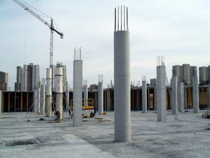
While rectangular and square sections are very popular in building construction due to the rectangular nature of walls, instances favouring circular or other column geometries do arise. For instance, for architectural reasons, standalone columns in the middle of halls or walkways are preferably circular due to aesthetic reasons. Furthermore, circular columns exhibit superior seismic performance compared to rectangular ones. A thorough understanding of these rationales is important for structural engineers and architects, particularly during the scheme development stage.

This knowledge facilitates informed decision-making regarding column geometry, thereby reducing the risk of inadequate construction work. It is to be emphasized that the selection of column geometry holds significant importance, similar to the determination of size, orientation, and positioning of both columns and beams within the structural system. While rectangular and circular columns satisfy the same structural functions, they offer distinct advantages and disadvantages in terms of strength, design considerations, and preferred applications.

Selection Criteria for Column Geometry in Building Construction
The configuration of a column’s cross-section, similar to other building elements, is governed by a multitude of factors such as architectural aesthetics, ease of construction, functional requirements, and structural demands.
Aesthetic Considerations
Architectural appeal is one of the prominent factors influencing column geometry. Square and rectangular columns can be easily placed within walls and covered with plastering, such that nobody will know that the columns were there in the first place. When square columns are not feasible due to structural size requirements, rectangular columns can be employed, such that the width will be equal to the width of the wall. This leads to a smooth flow and alignment of walls without undesirable projections.

On the other hand, circular sections are often favoured for their inherent visual harmony. However, their application is frequently confined to specific contexts such as luxury mansions, monumental buildings, educational institutions, verandas, and public buildings. Circular columns are preferable when the column element is standing alone since they will rarely blend into walls without projecting out of the wall lines.
Formwork Considerations and Cost Implications
There is a significant disparity between the construction of column formwork of rectangular/square and circular sections. Achieving a smooth, curved profile for circular columns demands enhanced craftsmanship and superior formwork materials, often including new plywood or aluminium systems.
This complexity translates to challenges in attaining a high-quality concrete finish. Likewise, plastering a curved surface to the desired level is considerably more intricate compared to a flat plane, leading to increased construction time and cost. Given the budgetary constraints inherent in many medium-scale projects, clients often prioritize cost-effectiveness, making rectangular/square columns more favourable.
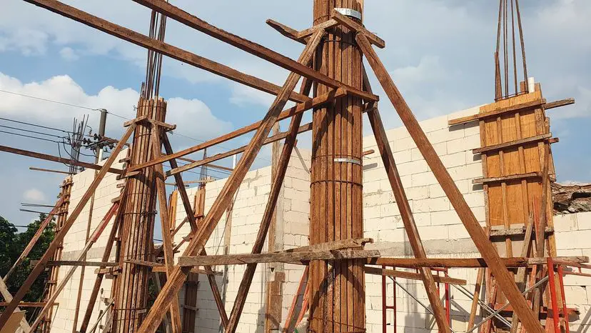
Furthermore, the pressure exerted on column formwork by fresh concrete can be more complicated when compared with square or rectangular sections. Consequently, stricter quality control measures and more elaborate formwork support systems are mandatory on-site. The increased level of workmanship required for these considerations translates to a significant cost increase compared to rectangular column construction.

Functional Requirements
The intended use of a space significantly influences column selection. In office environments, columns often serve as display surfaces for artwork, signage, or bulletin boards. Rectangular sections provide inherently planar surfaces ideal for such applications. This rationale extends to basement parking areas, where rectangular or square columns offer suitable flat surfaces for traffic flow notices, warnings, and signage – commonly observed in shopping malls and other commercial establishments.
Structural Considerations
While circular columns generally exhibit superior seismic performance, specific scenarios necessitate enhanced stiffness in a particular direction. This is particularly relevant for slender buildings with a limited base width and an extended length. To achieve this, engineers may favour a rectangular column with a larger dimension oriented towards the slender direction.
Moment of Inertia
A critical factor in column strength is the moment of inertia (I), a property that reflects a section’s resistance to bending. Circular columns boast a higher and more uniform I value across all axes compared to rectangular columns. This translates to superior resistance to bending moments and deflection, making them ideal for structures subjected to high lateral loads, such as bridges.

For rectangular sections, the moment of inertia (I) is given by;
I = bh3/12
For circular sections, the moment of inertia (I) is given by;
I = πD4/64
Let us consider a square column of dimensions 250 mm x 250 mm. This column will have an area of 0.0625 m2. A circular column that will produce a similar area will have a diameter of 282 mm.
The square section will have a moment of inertia I = bh3/12 = (0.25 × 0.253)/12 = 3.255 × 10⁻⁴ m4
The circular section will have a moment of inertia I = πD4/64 = (π × 0.2824)/64 = 3.104 × 10⁻⁴ m4
Therefore for sections of similar cross-sectional area, square sections have higher moment of inertia than circular sections.
Buckling Resistance
Another important aspect of strength consideration of columns is buckling, which is the tendency of a slender column to bend under compressive loads. Circular sections, due to their uniform distribution of material around the centroidal axis, offer superior buckling resistance compared to rectangular columns, especially when the load is not perfectly centred.
Material Efficiency
Rectangular columns, however, can be more material-efficient for specific loading conditions. By strategically orienting the rectangular section with the larger dimension towards the direction of higher bending moment, engineers can achieve optimal load-carrying capacity with less material compared to a circular column of equivalent area.
Reinforcement
Circular columns typically require more reinforcement bars due to their curved shape. While this can impact material costs, it also enhances their overall compressive strength.
Applications
Rectangular Columns:
- Widely used in buildings due to their ease of construction and efficient space utilization in confined areas.
- Preferred for load-bearing walls where columns can be integrated with the wall structure.
- Suitable for situations where higher bending moment capacity is required in a specific direction by adjusting the rectangular section.
Circular Columns:
- Ideal for bridge piers and other structures subjected to high lateral loads due to their superior bending and buckling resistance.
- Used in open spaces or architectural features where their aesthetic appeal is valued.
- Preferred in seismic zones due to their uniform distribution of strength across all axes.
Comparative Design of Square and Circular Columns
Investigate the design requirements of the two column cross-sections analysed above;
Square section = 250 x 250mm
Circular section = 282 mm (diameter)
Axial load = 1000 kN (No bending moment considered except secondary moments)
The effective length of the columns about the major and minor axis = 3000 mm√
Compressive strength of concrete = C20/25
Yield strength of reinforcement = 500 MPa
Square section design
Column slenderness about y-axis
Radius of gyration; iy = h/√(12) = 7.2 cm
Slenderness ratio (5.8.3.2(1)); ly = l0y / iy = 41.6
Column slenderness about z-axis
Radius of gyration; iz = b/√(12) = 7.2 cm
Slenderness ratio (5.8.3.2(1)); lz = l0z / iz = 41.6
Min end moment about y-axis; M01y = min(abs(Mtopy), abs(Mbtmy)) + eiyNEd = 7.5 kNm
Max end moment about y-axis; M02y = max(abs(Mtopy), abs(Mbtmy)) + eiyNEd = 7.5 kNm
Min end moment about z-axis; M01z = min(abs(Mtopz), abs(Mbtmz)) + eizNEd = 7.5 kNm
Max end moment about z-axis; M02z = max(abs(Mtopz), abs(Mbtmz)) + eizNEd = 7.5 kNm
Design bending moment about y-axis (cl. 5.8.8.2 & 6.1(4))
Nominal 2nd order moment; M2y = NEde2y = 14.3 kNm
M0ey = max(0.6M02y + 0.4M01y, 0.4M02y), max(0.6M02y – 0.4M01y, 0.4M02y)) = 7.5 kNm
Equivalent moment from frame analysis;
M0ey = max(0.6M02y + 0.4M01y, 0.4M02y) = 7.5 kNm
Design moment;
MEdy = max(M02y, M0ey + M2y, M01y + 0.5M2y, NEd × max(h/30, 20 mm))
MEdy = 21.8 kNm
Design bending moment about z-axis (cl. 5.8.8.2 & 6.1(4))
Nominal 2nd order moment; M2z = NEde2z = 13.4 kNm
M0ez = max(0.6M02z + 0.4M01z, 0.4M02z), max(0.6M02z – 0.4M01z, 0.4M02z)) = 7.5 kNm
Equivalent moment from frame analysis;
M0ez = max(0.6M02z + 0.4M01z, 0.4M02z) = 7.5; kNm
Design moment;
MEdz = max(M02z, M0ez + M2z, M01z + 0.5M2z, NEd × max(b/30, 20 mm))
MEdz = 20.9 kNm
Area of reinforcement provided = 6Y20 (Asprov = 1885 mm2)

Design axial resistance of section; NRd = (Acfcd) + (Asfyd) = 1527.9 kN
Ratio of applied to resistance axial loads; ratioN = NEd / NRd = 0.655
Exponent a = 1.46
Biaxial bending utilisation;
UF = (MEdy / MRdy)a + (MEdz / MRdz)a = 0.899
| Description | Unit | Provided | Required | Utilisation | Result |
| Moment capacity (y) | kNm | 34.23 | 21.84 | 0.64 | PASS |
| Moment capacity (z) | kNm | 40.43 | 20.88 | 0.52 | PASS |
| Biaxial bending utilisation | 0.90 | PASS |
Circular section design
Column slenderness about both axis
Radius of gyration; iy = iz = h / 4 = 7.1 cm
Slenderness ratio (5.8.3.2(1)); ly = lz = l0y / iy = 42.6
Ecc. due to geometric imperfections (y-axis); eiy = l0y /400 = 7.5 mm
Min end moment about y-axis; M01y = min(abs(Mtopy), abs(Mbtmy)) + eiyNEd = 7.5 kNm
Max end moment about y-axis; M02y = max(abs(Mtopy), abs(Mbtmy)) + eiyNEd = 7.5 kNm
Design bending moment about y-axis (cl. 5.8.8.2 & 6.1(4))
Nominal 2nd order moment; M2y = NEde2y = 12.8 kNm
M0ey = max(0.6M02y + 0.4M01y, 0.4M02y), max(0.6M02y – 0.4M01y, 0.4M02y)) = 7.5 kNm
Equivalent moment from frame analysis;
M0ey = max(0.6M02y + 0.4M01y, 0.4M02y) = 7.5 kNm
Design moment;
MEdy = max(M02y, M0ey + M2y, M01y + 0.5M2y, NEd × max(h/30, 20 mm))
MEdy = 20.3 kNm
Design bending moment about z-axis (cl. 5.8.8.2 & 6.1(4))
Nominal 2nd order moment; M2z = NEde2z = 12.8 kNm
M0ez = max(0.6M02z + 0.4M01z, 0.4M02z), max(0.6M02z – 0.4M01z, 0.4M02z)) = 7.5 kNm
Equivalent moment from frame analysis;
M0ez = max(0.6M02z + 0.4M01z, 0.4M02z) = 7.5 kNm
Design moment;
MEdz = max(M02z, M0ez + M2z, M01z + 0.5M2z, NEd × max(b/30, 20 mm))
MEdz = 20.3 kNm
Resultant design moment; MEd = √(MEdy2 + MEdz2) = 28.7 kNm
Area of steel provided = 6Y20 (Asprov = 1885 mm2)

| Description | Unit | Provided | Required | Utilisation | Result |
| Moment capacity (y) | kNm | 30.11 | 20.31 | 0.67 | PASS |
| Moment capacity (z) | kNm | 31.68 | 20.31 | 0.64 | PASS |
| Combined capacity | kNm | 30.11 | 28.72 | 0.95 | PASS |
As can be seen from the design results, under similar axial loading and support conditions, square columns and circular columns of equal area will demand approximately the same area of reinforcement. However, once uniaxial and bi-axial bending moments are involved, we should expect a completely different behaviour in the quantity of reinforcements required.
Conclusion
The choice between rectangular and circular columns depends on a project’s specific requirements. When prioritizing strength and buckling resistance for structures like bridges or seismic zones, circular columns are often favoured. However, for ease of construction, space optimization, and cost-effectiveness in buildings, rectangular columns are the preferred choice. Understanding the strengths and limitations of each shape allows engineers to make informed decisions for optimal structural performance and aesthetics.
In conclusion, the selection of column cross-sectional geometry necessitates a comprehensive evaluation involving architectural intent, functional considerations, and structural demands. While aesthetics may favour circular columns in specific scenarios, the complexities and cost implications associated with formwork often render rectangular/square sections the more pragmatic choice for many building projects.





well explained