Arches are captivating structural elements, renowned for their elegance and efficiency in spanning large distances. However, their analysis becomes more complicated when they possess additional internal supports or fixed ends, leading to statically indeterminate structures.
Arches can be constructed using a variety of materials such as reinforced concrete, steel, or timber. Reinforced concrete arch bridges offer a viable solution for bridge systems spanning large distances. Arches are occasionally employed in roof structures, but their primary use lies in bridges.
There is a spectrum of arch configurations to satisfy different design needs. These configurations can be broadly categorized by the number of hinges present:
- Three-hinged arches: These arches possess the simplest support condition, with hinges at both ends and one at the crown. Three-hinged arch structures are statically determinate, which makes the analysis easier.
- Two-hinged arches: These arches incorporate hinges at only two locations, typically at the supports. This additional constraint introduces static indeterminacy, requiring more advanced analysis techniques.
- Fixed-end arches: These arches are rigidly connected to their supports, preventing rotations. This configuration offers superior load-carrying capacity but necessitates the most complex analytical methods due to static indeterminacy.
Arches can be further classified based on their geometric properties:
- Symmetry: The arch can be symmetrical about its central axis, offering a balanced aesthetic and potentially simplified analysis. Conversely, unsymmetrical arches may be required for specific site constraints.
- Alignment: An arch structure can be right-angled, following a straight line, or skewed, deviating from a straight path to accommodate topographical features.
- Singularity or Repetition: An arch bridge may consist of a single arch or a series of interconnected arches, often employed for longer spans. These interconnected arches may exhibit a degree of mutual dependence in their load-carrying behaviour, requiring careful consideration during analysis and construction.
This article is focused on the structural analysis of statically indeterminate arch structures.
Statically Indeterminate Arch Structures
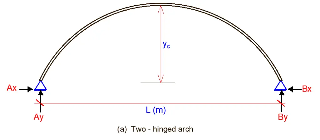
The figure below shows various configurations of statically indeterminate arches, comprising:
- two-hinged arches with and without tie rods,
- a one-hinged arch, and
- an arch with fixed supports.


The force method in its canonical form is the most effective approach for analyzing statically indeterminate arches. The number of unknown variables in this method directly correlates to the number of hinges present in the arch:
- Two-hinged arches: One primary unknown
- One-hinged arches: Two unknowns
- Hingeless arches (fixed ends): Three unknowns
In three-hinged arches specifically, the distribution of internal forces is heavily influenced by the shape of the neutral line (e.g., parabolic, circular). This characteristic must be factored into the calculation of unit coefficients and free terms within the canonical equations. In the general case, these coefficients and terms depend on bending moments, shear forces, and axial forces within the structure.
Notably, when calculating displacements, only bending moments in the arch itself and the axial force in any tie rod are considered, while shear and axial forces within the arch itself can be neglected.
The inherent curvature of the arch axis introduces limitations when employing the graph multiplication method, leading to approximate results. Unlike three-hinged arches, redundant arches (those with a higher number of unknowns than equilibrium equations) – akin to any statically indeterminate structure – experience internal forces due to factors beyond applied loads.
These factors include support displacements, temperature difference, and fabrication errors. In the case of masonry or concrete arches, concrete shrinkage must be specifically considered, as this material property contributes to the generation of additional stresses within the structure.
Steps in the Analysis of Indeterminate Arches
The procedure for analysis of statically indeterminate arches is as follows:
- Choose the primary system of the force method.
- Accept the simplified model of the arch, i.e., the arch is divided into several portions and each curvilinear portion is changed by straight member. Calculate the geometrical parameters of the arch at specified points.
- Calculate the unit and loaded displacements, neglecting the shear and axial forces in arch. Computation of these displacements may be performed using the graph multiplication method.
- Find the primary unknown using canonical equations of the force method.
- Construct the internal force diagrams.
- Calculate the reactions of supports and provide their verifications.
Solved Example
A two-hinged arch structure is loaded as shown below. Obtain the support reactions, bending moments, shear force, and axial force diagrams at the designated critical points (1, 2, C, 3 and 4). EI = Constant

Solution
A two-hinged arch is statically indeterminate to the first degree. A primary system can be obtained by removing one of the horizontal supports. The primary unknown X1 is therefore taken as the horizontal reaction at support A.

Geometrical properties of the arch
The ordinate (y) at any point along a parabolic arch is given by;
y = [4yc (Lx – x2)] / L2
Where;
yc = Height of the crown of the arch from the base
L = Length of arch
x = Horizontal ordinate of interest
Hence, y = [4 × 8 (45x – x2)] / 452
The general equation of the arch now becomes;
y = 0.7111x – 0.0158x2 ———- (1)
Differentiating equation (1) with respect to x
dy/dx = y’ = 0.7111 – 0.0316x ———— (2)
From trigonometric relations, we can verify that;
Sin θ = y’/[1 + (y’)2]0.5 —————- (3)
Cos θ = 1/[1+ (y’)2]0.5 —————- (4)
From the above relations, we can carry out the calculations for obtaining the geometrical properties of the arch structure.
Let us consider point A (support A of the structure);
Point A:
x = 0, and y = 0;
From equation (2) above, y’ = 0.7111;
Thus,
Sin θ = 0.7111/[1 + (0.7111)2]0.5 = 0.579
Cos θ = 1/[1 + (0.7111)2]0.5 = 0.815
Point 2:
x = 7.5m
From equation (1), y = 0.7111(7.5) – 0.0158(7.5)2 = 4.444 m;
dy/dx = y’ = 0.7111 – 0.0316(7.5) = 0.4741
Thus,
Sin θ = (0.4741)/[1 + (0.4741)2]0.5 = 0.4284
Cos θ = 1/[1 + (0.4741)2]0.5 = 0.903
For the entire arch structure, it is more convenient to set out the geometrical properties in a tabular form. See the Table below;
| Point | x (m) | y (m) | y’ | √[1 + (y’)2] | sin θ | cos θ |
| A | 0 | 0 | 0.7111 | 1.227 | 0.5795 | 0.815 |
| 1 | 7.5 | 4.444 | 0.4741 | 1.1067 | 0.4284 | 0.903 |
| 2 | 15 | 7.111 | 0.2371 | 1.0277 | 0.2307 | 0.973 |
| C | 22.5 | 8.000 | 0.000 | 1.000 | 0.000 | 1.000 |
| 3 | 27.5 | 7.606 | -0.1579 | 1.012 | -0.156 | 0.988 |
| 4 | 35 | 5.533 | -0.3949 | 1.075 | -0.367 | 0.930 |
| B | 45 | 0 | -0.711 | 1.227 | -0.5795 | 0.815 |
The length of the chord between points n and n-1 equals;
ln,n-1 = √[(xn – xn-1)2 + (yn – yn-1)2]
la-1 = √[(7.5 – 0)2 + (4.444 – 0)2] = 8.7177 m
l1-2 = √[(15 – 7.5)2 + (7.111 – 4.444)2] = 7.96 m
l2-c = √[(22.5 – 15)2 + (8 – 7.111)2] = 7.5525 m
lc-3 = √[(27.5 – 22.5)2 + (7.606 – 8)2] = 5.015 m
l3-4 = √[(35 – 27.5)2 + (5.533 – 7.606)2] = 7.7812 m
l4-b = √[(45 – 35)2 + (0 – 5.533)2] = 11.428 m
Analysis of Case 1 (Unit State)
X1 = 1.0

Mi = -1.0y
Qi = -1.0 sin θ
Ni = -1.0 cos θ
The internal stresses due to the unit state can be tabulated as shown below.
| Point | M | Q | N |
| A | 0.00 | -0.597 | -0.815 |
| 1 | -4.444 | -0.4284 | -0.903 |
| 2 | -7.111 | -0.2307 | -0.973 |
| C | -8.000 | 0.000 | -1.000 |
| 3 | -7.606 | 0.156 | 0.988 |
| 4 | -5.533 | 0.367 | -0.930 |
| B | 0.000 | 0.597 | -0.815 |
Loaded State;

Support Reactions
Let ∑MB = 0; anticlockwise negative
(Ay × 45) – (12 × 37.5) – (2 × 22.5 × 11.25)= 0
Therefore, Ay = 21.25 kN
Let ∑MA = 0; clockwise negative
(By × 45) – (12 × 7.5) – (2 × 22.5 × 33.75) = 0
Therefore, By = 35.75 kN
Let ∑Fx = 0;
Hence, Bx = 0
Internal Stresses
Bending Moment
MA = 0 (hinged support)
M1 = (21.25 × 7.5) = 159.375 kN.m
M2 = (21.25 × 15) – (12 × 7.5) = 228.75 kN.m
MC = (21.25 × 22.5) – (12 × 15) = 298.125 kNm
Coming from the right-hand side;
MC = (35.75 × 22.5) – (2 × 22.5 × 11.25) = 298.125 kNm
M3 = (35.75 × 17.5) – (2 × 17.5 × 8.75) = 319.375 kN.m
M4 = (35.75 × 10) – (2 × 10 × 5) = 257.5 kN.m
MB = 0 (hinged support)
Shear
Q = ∑V cosθ
QA = (21.25 × 0.815) = 17.318 kN
Q1L = (21.25 × 0.903) = 19.188 kN
Q1R = [(21.25 – 12) × 0.903)] = 8.352 kN
Q2 = [(21.25 – 12) × 0.973)] = 9.00 kN
QC = [(21.25 – 12) × 1.000)] = 9.25 kN
Q3 = [(21.25 – 12 – 2×5) × 0.988)] = -0.741kN
Q4 = [(21.25 – 12 – 2×12.5) × 0.930)] = -14.647 kN
QB = [(21.25 – 12 – 2×22.5) × 0.815)] = -29.136 kN
Axial
N = -∑V sinθ
QA = -(21.25 × 0.5795) = -12.314 kN
Q1L = -(21.25 × 0.4284 = -9.103 kN
Q1R = -[(21.25 – 12) × 0.4284)] = -3.9627 kN
Q2 = -[(21.25 – 12) × 0.2307)] = -2.134 kN
QC = -[(21.25 – 12) × 0.000)] = 0 kN
Q3 = -[(21.25 – 12 – 2×5) × -0.156)] = -0.117 kN
Q4 = -[(21.25 – 12 – 2×12.5) × -0.367)] = -5.780 kN
QB = -[(21.25 – 12 – 2×22.5) × -0.5795)] = -20.717 kN
The Table of the bending moment in the unit and loaded state are shown below;
| Point | M1 (unit state) | Mp (loaded state) |
| A | 0.00 | 0.000 |
| 1 | -4.444 | 159.375 |
| 2 | -7.111 | 228.75 |
| C | -8.000 | 298.125 |
| 3 | -7.606 | 319.375 |
| 4 | -5.533 | 257.5 |
| B | 0.000 | 0.000 |
The canonical equation for the structure is given by;
δ11X1 + ∆1P = 0
Computation of unit and loaded displacements
For the calculation of displacements, the Simpson’s formula can be employed. Unit and loaded displacements are;

where;
li is the length of the ith straight portion of the arch;
n number of the straight portions of the arch;
a1, aP ordinates of the bending moment diagrams M1 and MP at the extreme left end of the portion;
b1, bP ordinates of the same bending moment diagrams at the extreme right end of the portion; and
c1, cP are the ordinates of the same bending moment diagrams at the middle point of the portion.
| Portion | l/6E1 | a1 | c1 | b1 | ap | cp | bp | δ11 | ∆1P |
| A-1 | 1.452 | 0.00 | -2.222 | -4.444 | 0.000 | 79.6875 | 159.375 | 57.351 | -2056.79 |
| 1-2 | 1.327 | -4.444 | -5.777 | -7.111 | 159.375 | 194.0625 | 228.75 | 270.456 | -9049.21 |
| 2-C | 1.259 | -7.111 | -7.555 | -8.000 | 228.75 | 263.4375 | 298.125 | 431.683 | -15073.65 |
| C-3 | 0.8358 | -8.000 | -7.803 | -7.606 | 298.125 | 308.75 | 319.375 | 305.400 | -12078.03 |
| 3-4 | 1.297 | -7.606 | -6.569 | -5.533 | 319.375 | 288.4375 | 257.5 | 338.610 | -14828.46 |
| 4-B | 1.905 | -5.533 | -2.766 | 0.000 | 257.5 | 128.75 | 0.000 | 116.618 | -5427.797 |
| Total | 1520.121/EI | -58513.96/EI |
δ11X1 + ∆1P = 0
1520.121X1 – 58513.96 = 0
X1 = 58513.96/1520.121 = 39.492 kN
X1 is the unknown horizontal reaction (thrust) at support A. The final bending moment, axial, and shear force values can be computed by following the first principle, or by applying the equations below;
Mf = M1X1 + M0
Qf = Q1X1 + Q0
Nf = N1X1 + N0
Final Bending Moment
| Point | M1 (unit state) | M0 (loaded state) | M1X1 + M0 (kNm) |
| A | 0 | 0 | 0 |
| 1 | -4.444 | 159.375 | -16.127 |
| 2 | -7.111 | 228.75 | -52.07 |
| C | -8 | 298.125 | -17.81 |
| 3 | -7.606 | 319.375 | 18.99 |
| 4 | -5.533 | 257.5 | 38.99 |
| B | 0 | 0 | 0 |
Final Shear Force
| Point | Q1 | Q0 | Q1X1 + Q0 (kN) |
| A | -0.597 | 17.318 | -6.258 |
| 1L | -0.4248 | 19.188 | 2.411 |
| 1R | -0.4284 | 8.352 | -8.56 |
| 2 | -0.2307 | 9 | -0.11 |
| C | 0 | 9.25 | 9.25 |
| 3 | 0.156 | -0.741 | 5.419 |
| 4 | 0.367 | -14.647 | -0.153 |
| B | 0.597 | -29.136 | -5.559 |
Final Axial Force
| Point | N1 | N0 | N1X1 + N0 (kN) |
| A | -0.815 | -12.314 | -44.49 |
| 1L | -0.903 | -9.103 | -44.76 |
| 1R | -0.903 | -3.9627 | -39.62 |
| 2 | -0.973 | -2.134 | -40.55 |
| C | -1 | 0 | -39.49 |
| 3 | 0.988 | -0.117 | 38.901 |
| 4 | -0.93 | -5.78 | -42.50 |
| B | -0.815 | -20.717 | -52.90 |
Software Applications
Due to the complexities involved in the analysis of indeterminate arch structures, structural analysis software plays a crucial role in practical applications. Popular software packages such as Staad Pro, SAP2000, RISA-3D, and Abaqus offer powerful tools for analyzing statically indeterminate arches. These software tools can handle a wide range of material properties, loading conditions, and geometric complexities, enabling efficient and accurate analysis.


