Simple duplex buildings that are founded on soil with an allowable bearing capacity of 100 kN/m2 and above can be safely and economically supported on pad foundations. This article is aimed at proposing an alternative to the method of construction of foundations of duplexes on good soil (say, safe bearing capacity of 100 kN/m2 and above) in Nigeria.
In Nigeria, the most popular approach to the construction of the foundation of duplexes is the combination of pad foundation and strip foundation. Pad foundations are used to support the columns of the building, while the strip foundation is used to support the block wall (sandcrete masonry units).
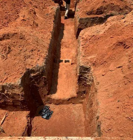
Typically, the size of a pad foundation depends on the expected service load coming from the column, the safe bearing capacity of the soil, and the allowable settlement (whichever governs the design). The thickness of the foundation and the reinforcements required is determined from ultimate limit state considerations such as bending, one-way shear, and punching shear.
On the other hand, the width of strip footings in the foundation of duplexes is usually kept between 675mm – 700 mm. The thickness of the concrete ranges from 150 mm to 225 mm if 9 inches hollow blocks are used. When the depth of the water table is very low below the surface, the depth of the foundation is usually kept between 900 mm and 1200 mm.
Since the strips are usually unreinforced, the recommended thickness of the strip foundation for 9 inches blocks (225 mm blocks) is about 225 mm, such that the pressure dispersal (at 45 degrees) will hit the edges of the foundation without introducing any punching shear (see Figure 2). This recommended option can be economically challenging during the construction of strips for duplexes and the advice of a structural engineer should be sought before a decision is taken.
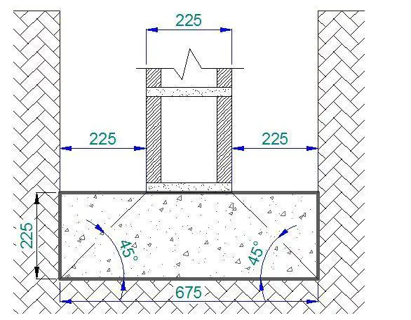
During the structural design of residential duplexes, it is usually assumed that masonry units (block walls) do not carry any load (framed structure) even though sometimes construction methodology may suggest otherwise. Therefore at the foundation, we expect the strip footing to carry at most the self-weight of the ground floor wall and finishes, which is usually about 10.5 kN/m for a 3m high wall. The ground floor slab load may be transmitted to the strip foundation too.
Generically, the total load transmitted to the strip footing depends on the structural scheme and the construction methodology. For instance, some designers/builders prefer to chain foundations at the damp-proof course (DPC) level. In this case, the entire block wall load of the ground floor is not expected to be transmitted to the strip foundation, but to the columns through the plinth beams.
The Conventional Process of Constructing the Foundation of Duplexes in Nigeria
(a) Setting out
When it has been determined that pad foundations can be used to support a duplex in an area of low water table, the first step in the construction of the foundation is the ‘setting out’. For a regular duplex building, setting out can be achieved using wooden pegs and 2″ x 3″ softwood as the profile board (See Figure 3).
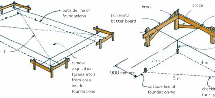
Using the 3-4-5 method, builders’ square, and lines, the building can be set out accurately. Where available, total stations and laser setting out/levelling equipment can be used to make the job faster. The width of excavation, building lines, and wall centrelines are all established on the profile board using nails as shown in Figure 4.
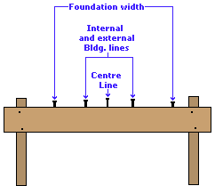
It is important to keep the profile board in place until the ground floor slab is cast. Furthermore, it can also be helpful to transfer reference levels and at least two coordinates (building lines/axes in both directions) to a permanent place peradventure you will need them later after the removal of the profile board.
(b) Excavation
After setting out the building, the next step is to commence excavation. The width of excavation is transferred from the profile board, while the depth of the foundation is determined from the design drawings. Using the reference level, the depth of the foundation is established by the site engineer. If the ground is sloping, the foundation can be stepped with the approval of the design engineer.
It may be possible to excavate the column bases first before the strip or vice versa. But in each case, some portion of the excavated soil must be moved away in order to accommodate the other. From experience, it may be handier to excavate the strips first before excavating the column bases.
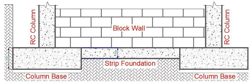
In order to have a flat surface for laying blocks, the column bases may have to go deeper than the strips. For instance, if the column base is 300 mm thick, and the strip 150 mm thick, the column base may be stepped down by 200 mm (an additional 50 mm for the blinding) so that when it is cast, it will flush with the level of the strip as shown in Figure 5. For the foundation layout being considered, the excavation works should cost about ₦130,400 using manual labour.
(c) Leveling and Compaction of the Excavated Trenches
After the excavation of the trenches, the foundation base should be properly compacted and levelled to receive concrete. The levelling should ensure that the thickness of the concrete is the same wherever required. Wooden pegs or short reinforcement offcuts can be used to establish the required levels. Range and spirit level or laser can be used to transfer the levels from one point to another. For shallow foundations in lateritic or cohesive soils, the excavation should be able to stand on its own without caving in within the 900 – 1200 mm depth. If the foundation is founded on sand, side supports for the excavation will be required.
(d) Blinding
The column base should be blinded using concrete of the same strength as the foundation. The thickness of the blinding should be about 50 mm thick and should be properly consolidated.
(e) Reinforcement Works
The column base reinforcements and the starter bars should be prepared according to the structural drawing. Using the profile board and lines, the starter bars should be mounted in their correct position to avoid cranking of reinforcement later. The site engineer should ensure that the column starter bars are plumb and properly braced to prevent movement during concreting.
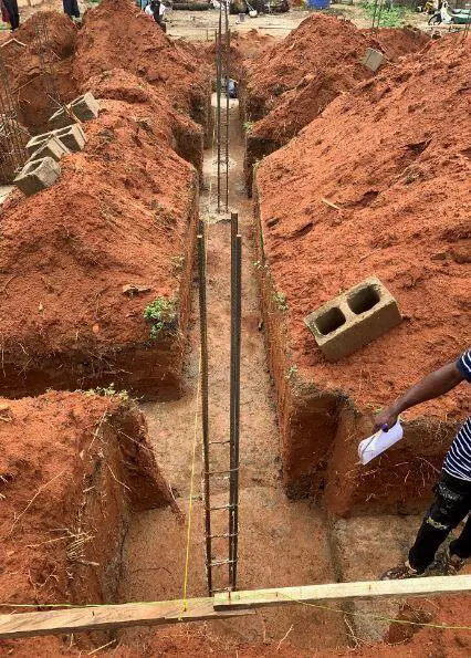
The design engineer and the consulting architect should sign off the placement of the reinforcements after the iron benders are done. While the architect should check setting out and positioning, the structural engineer should check out the following;
(1) The blinding was properly done
(2) The correct bar size, yield strength, and spacing were used for the reinforcements. The Consulting Engineer should request the reinforcement tensile strength test result.
(3) Adequate concrete cover (50 mm) has been provided under the column base reinforcement, away from the blinding.
(4) The column starter bars are centrally positioned on the basket (or according to the drawings) to avoid eccentric loading on the foundation.
(5) The foundation has been pegged and excavated such that the thickness of the concrete when poured will meet the design specifications.
If the reinforcement placement is found satisfactory, approval should be given for concreting.
(f) Concreting
The strip foundation and the column bases should be poured to the specified thickness using the recommended concrete grade. The concrete should be properly vibrated to ensure that minimal voids exist in the concrete mass. An experienced mason should dress the surface and ensure that the established casting levels are properly followed.
(g) Blockwork
After the concreting, the blockwork should be done according to the drawings from the foundation up to the DPC level. The site engineer should ensure that the edges of the block adjacent to the column maintain a concrete cover of about 35 mm. Furthermore, the size of the column obtained should be consistent with the design specifications, since the blocks act as part of the permanent formwork for the column. The edges of the block close to the column should be perfectly aligned and plumb. Some engineers recommend filling the hollow sandcrete blocks with weak concrete.
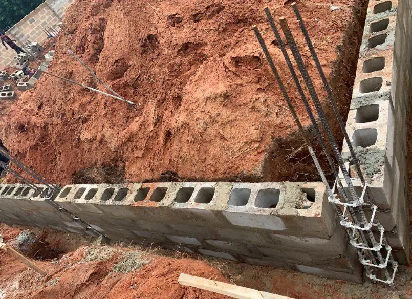
(h) Casting of the column stubs
After the blockwork is complete, the column stubs should be cast. Before this is done, it is important to clean up all the soil that must have entered the base of the column preferably using a high-pressure water jet. This must be done before the carpenter places the formwork. The formwork for the column stubs must be properly braced to avoid bursting during the concrete pouring. The recommended concrete mix should be used, and be properly vibrated to avoid honeycombs.
(i) Backfilling and Compaction
The foundation is usually backfilled using the material excavated from the foundation. To make up level up to the DPC, high-quality lateritic materials or sand should be imported, placed, and compacted up to the required level. The earth material to be used should be non-expansive or problematic. After this process, the damp proof membrane should be installed, and hardcore/BRC wire mesh installed as recommended in the design specification.
(j) Casting of the ground-floor slab
Carpenters should prepare the edge formwork of the building and ensure that it is perfectly level. Levels should also be established internally so that the final surface of the ground floor slab will be flat. After this, the ground floor concrete is poured and finished as appropriate.
The casting of the ground-floor slab process completes the substructure works.
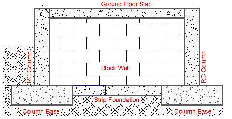
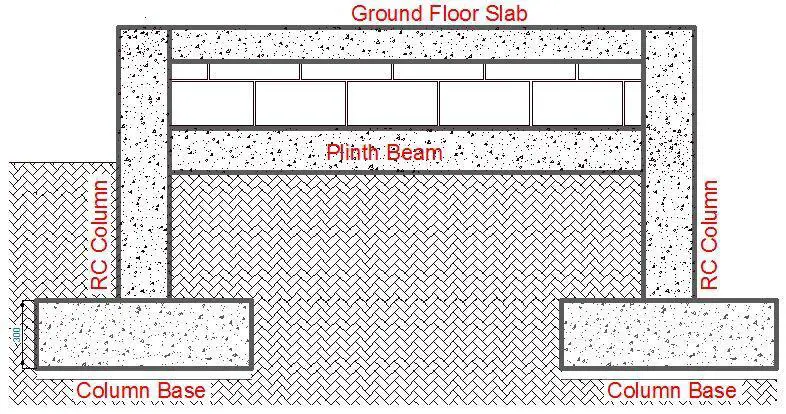
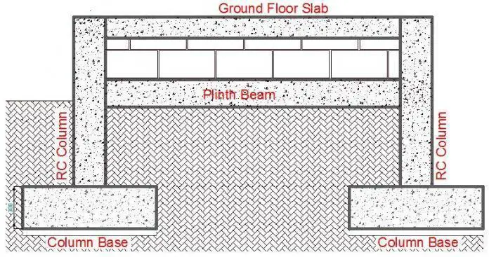
We can see that the process can be quite lengthy, and normally takes about one week to complete if there are no unnecessary delays and if an adequate workforce is used. A schematic representation of the final output is shown in Figure 8.
Alternative Approach to Duplex Foundation Construction
If we theoretically assume that block walls do not carry any load, why do we go through the lengthy process of excavating the strips, casting the strip, and forming block walls from the foundation up to the DPC level? The new approach to be recommended in this section intends to boycott this process and probably save cost, and make the construction process faster. This approach may already be in practice somewhere else. The new approach is outlined below;
(1) Setting out
The setting out process is the same as outlined above, but the excavation lines for the width of the strip may be omitted.
(2) Excavation and blinding
At this stage, only the column bases will be excavated to the required depth, and the concrete for blinding poured as technically specified.
(3) Reinforcement Works
The reinforcement works for the column base and column starter bars should be prepared and installed as described in the approach above.
(4) Casting of the column base and stubs
The column base concrete should be poured first and the following day, 75mm thick kickers that depicts the dimensions and orientation of the columns should be formed. The column stub formwork should be installed and properly braced before the concreting of the column stub is done. The height of the column should be up to the grade level or as technically recommended.
(5) Casting of plinth beams
Reinforced concrete plinth beams should be cast near the ground level surface to receive the block walls that will go up to the required ground floor level. The ground to receive the plinth beams should be well prepared, levelled, and made firm to receive the blinding before the beam is cast. The plinth beams should run from column to column and to areas where blockwork is expected. The width of the beam should be the same width as the block to be used or larger. The depth can be determined by the structural engineer but is not expected to exceed 300 mm.
(6) Blockwork
Blockwork is laid from the plinth beam to the required DPC level. After which the filling, compaction, and casting of the ground floor are done. A schematic representation of the final output is shown in Figure 8.
Cost Comparison of both Alternatives
Let us now compare the cost of adopting both approaches in the construction of a duplex with the foundation layout shown in Figure 10.
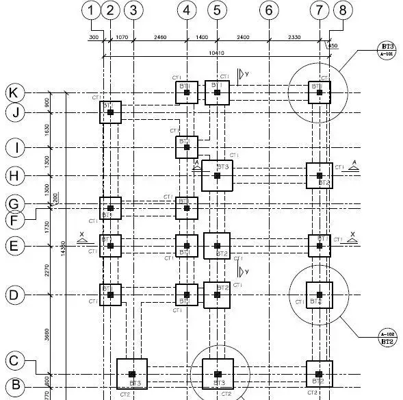
Constructing a plinth beam and ignoring strip foundation for the substructure layout shown in Figure 10 will incur the following costs;
(1) Cost of minor excavation and leveling of ground (say) = ₦20,000
(2) Concrete required = 6m3 × ₦42,500 = ₦255,000
(3) Y12 mm reinforcement required = 405 kg × ₦450 = ₦182,250
(4) Y8 mm required as links = 162 kg × ₦450 = ₦72,900
(5) Binding wire (say) = ₦13,000
(6) Formwork required 58 m2 of 1″ x 12″ planks = 58 m2 × ₦1905 = ₦110,490
(7) Bracing required 20 pcs pf 2″ x 3″ wood = 20 × ₦400 = ₦8000
(8) Total Labour and supervision cost = ₦120,000
Total cost of construction = ₦781,640
Alternatively, when the strip foundation is used, the likely costs are as follows;
(1) Excavation of strip foundation = ₦100,000
(2) Concrete required for the strip = 13.5 m3 × ₦42,500 = ₦573,750
(3) Blockwork to the ground level = 103 m2 × ₦3,700 = ₦381,100
(4) Backfilling of strip foundation (say) = ₦10,000
(5) Total Labour cost (concrete and block work) = ₦149,900
(6) Supervision cost (say) = ₦50,000
Total cost of construction = ₦1,264,750
Therefore using grade supported plinth beams to support blockwork instead of strip foundation in the substructure of a duplex can lead to savings in the cost of the substructure by about 38%.








Cost of blocks is not included in the plinth beam option calculations. Won’t that result to almost the same cost implications if added.
Thank your the great job you’re doing.
The plinths are on grade, and we can only have blocks that will go from the grade level to the DPC. The cost of those blocks were neglected in both calculations.
Good morning Engr. I love this article, and I have a question. my question is what if one decided to do the strip footing only for external walls only, lay the block for the external only to a level below the DPC but above GL, fill solid, then backfill, compact in 3 layers, then introduction the plinth beam connecting the whole columns, then pour the hardcore/BRC wire mesh then the ground floor slab. Will it still achieve that suppose?
Good job Engr, my question is what if one decides to excavate strip for the external walls (perimeter walls) only then follow the normal process lay your blocks up to a level above the GL but below your DPC, then fill solid, backfill the area with good material, compact at least in three layers, then cast the plinth beams connecting every column or where the wall are supposed to be laid, then pour ur hardcore/BRC wire mesh, then pour the ground slab. will this be economical and safe too? Thanks
This is a fantastic alternative too. Another advantage of this method is that it will help reduce scouring at the foot of the foundation.
Good day, Engnr. Is it necessary to do what they call chaining of foundation for a 2-storey building on a gravel and non-clay soil? The area has no history of cracking walls.
It is not necessary
well-done
Hello Engr, is there a risk of scouring around the plinth beam since is very close to the NGL? if yes, how can we prevent it?. Thank you
Obviously, the risk of scouring around the plinth beam is there. So many measures can be adopted to prevent it such as placing the bottom of the beam below the compound level before filling.
greetings engr. must one hardcore for a storey building? even if the soil is good?