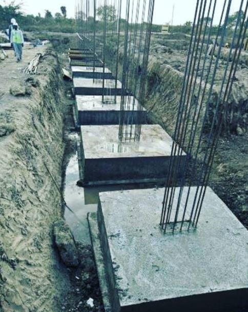
Pad foundations are isolated rectangular, square, or circular slabs that are provided under reinforced concrete columns or column stubs to safely transmit the column load to the ground. They are a type of shallow foundation that is widely used all over the world especially in areas where the soil possesses good bearing capacity. They are also referred to as isolated bases or spread footings. The design of pad foundations involves sizing the base slab to satisfy geotechnical requirements and providing adequate thickness and reinforcements to satisfy structural requirements.
The dimensions of a pad foundation should not be too small so as to cause excessive settlement or bearing capacity failure of the soil. As a matter of fact, allowable bearing capacity is normally used to control settlement during the design of a pad foundation, hence it is treated as a serviceability limit state parameter. The width of a pad foundation is expected not to be less than 1000 mm, and the thickness not less than 150 mm.
Geotechnical Design of Pad Foundation
The geotechnical design of a pad foundation can be carried out according to the requirements of EN 1997-1:2004 (Eurocode 7). Eurocode 7 gives three approaches for the geotechnical design of foundations and they are as follows;
Design Approach 1 (DA1): In this approach, partial factors are applied to actions and to ground strength parameters.
Design Approach 2 (DA2): In this approach, partial factors are applied to actions or to the effects of actions and to ground resistances.
Design Approach 3 (DA3): In this approach, partial factors are applied to actions or to the effects of actions from the structure and to ground strength parameters.
The three approaches can give very different results when applied in design. However, the UK National Annex to Eurocode 7 permits only Design Approach 1 (DA1). For the design of pad foundation using Design Approach 1, three limit states with their appropriate load combination shall be satisfied for the structure. These limit states are;
EQU: Loss of equilibrium of the structure
STR: Internal failure or excessive deformation of the structure itself
GEO: Failure due to excessive deformation of the ground supporting the structure
UPL: Failure due to uplift of the foundation due to water pressure
HYD: Failure due to hydraulic gradient
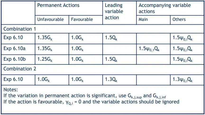
In the design of pad foundation using DA1, there are two sets of limit state combinations for STR and GEO limit states. Combination 1 is normally used for the structural design of the foundation, while combination 2 is normally used for sizing the foundation. The partial factors for the limit states are given in the table below;
The partial factors for EQU, UPL, and HYD are given in the Table below. They can also be used in the uplift verification of all kind of buried structures.

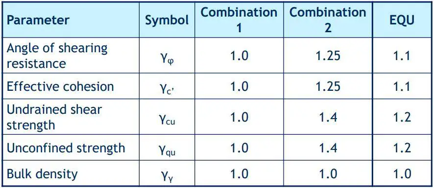
The partial factors for soil properties is given in the table below;
It should be noted that pad foundations fall under category 2 structures which means that they are conventional structures that are founded on non-difficult grounds. They offer no exceptional geotechnical risk. As a result, routine procedures for field and laboratory testing for design and execution may be used. Geotechnical design of pad foundations can be done by geotechnical or structural engineers. However, the geotechnical design of category 3 structures with abnormal risk can be done by geotechnical engineers only.
The design of pad foundations can be done using any of the following methods;
(a) Analytical (Direct) method
(b) Semi-empirical (Indirect) method
(c) Prescriptive method using presumed bearing resistance (BS 8004)
Using the analytical (direct) method, all limit states should be verified. The ultimate bearing capacity qult of a pad foundation should be verified using the expression below;
qult = c’Ncscdcicgcbc + q’Nqsqdqiqgqbq + γ’BNγsγdγiγgγbγ/2
where;
c = cohesion
q = overburden
γ = body-weight
Ni = bearing capacity factors
si = shape factors
di = depth factors
ii = inclination factors
gi = ground inclination factors
bi = base inclination factors
Example on the calculation of the bearing capacity of a pad foundation using Design Approach 1 (DA1)
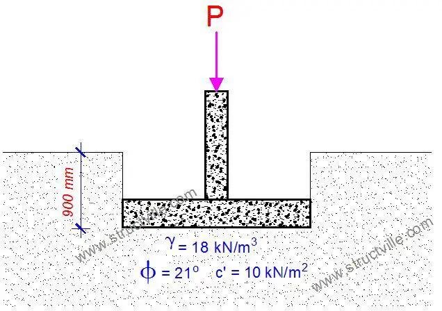
Calculate the bearing capacity of a 1m x 1m pad foundation founded at 0.9 m below a lateritic soil deposit. The characteristic angle of shearing resistance φk of the soil is 21° while the effective cohesion c’ is 10 kN/m2. The water table is 8m below the ground surface, and the unit weight of the soil is 18 kN/m3.
Solution
As the footing rests on a cohesive-frictional soil, the relevant material property is the angle of shearing resistance, φ and the effective cohesion c’.
Design values of angle of shearing resistance
Characteristic value φk = 21°. Note that the safety factor γφ is applied to tan φk not to φk.
Combination 1: γφ = 1.0, tan φd = tan φk/γφ= tan 21° = 0.383, φd = 21°
Combination 2: γφ = 1.25, tan φd = tan φk/γφ = tan 21/1.25 = 0.307, φd = 17°
Design values of cohesion
Characteristic value of effective cohesion c‘ = 10 kN/m2
Combination 1: γc’ = 1.0, c’d = c’/γc’ = 10 kN/m2
Combination 2: γc’ = 1.25, c’d = c’/γc’ = 10/1.25 = 8 kN/m2
Step 2: Calculate design bearing capacity factors. Use the equations in section D.4 of Annex D of Eurocode 7.
i. Overburden factor Nq
Nq = e(π × tanφd) × tan2 (45 + φd/2)
Combination 1: φd = 21°, Nq = 7.07
Combination 2: φd = 17°, Nq = 4.77
ii. Cohesion factor, Nc
Nc = (Nq − 1) cot φd
Combination 1: φd = 21°, Nc = 15.84
Combination 2: φd = 17°, Nc = 12.28
iii. Body weight factor Nγ
Nγ = 2(Nq − 1) tanφd
Combination 1: φd = 21°, Nγ = 4.66
Combination 2: φd = 17°, Nγ = 2.305
Step 3: Calculate the design shape factors. Use the equations in Annex D of Eurocode 7.
Square base
i. sq = 1 + sin φd
Combination 1: φd = 21°, sq = 1.358
Combination 2: φd = 17°, sq = 1.292
ii. sc = (sqNq − 1)/(Nq − 1)
Combination 1: Nq = 7.07, sq = 1.358, sc = 1.419
Combination 2: Nq = 4.77, sq = 1.292, sc = 1.369
iii. sγ = 0.7 (for a square shape)
Step 4: Calculate the overburden pressure, q.
The unit weight of soil is 18 kN/m3 and the safety factor γγ = 1
q = 18 × depth of footing = γγ × 18 × 0.9 = 16.2 kN/m2
Step 5: Calculate the allowable qult:
qult = c’Ncscdcicgcbc + q’Nqsqdqiqgqbq + γ’BNγsγdγiγgγbγ/2
For this calculation, all inclination factors have been ignored.
qult = c’Ncsc + q’Nqsq + 0.5γ’BNγsγ
Combination 1: qult = (10 × 15.84 × 1.419) + (16.2 × 7.07 × 1.358) + (0.5 × 18.0 × 4.66 × 1.0 × 0.7) = 409.66 kN/m2
Combination 2: qult = (8 × 12.28 × 1.369) + (16.2 × 4.77 × 1.292) + (0.5 × 18.0 × 2.305 × 1.0 × 0.7) = 248 kN/m2
For sizing of the foundation, Combination 2 allowable bearing capacity should be used (no other factor of safety is to be applied).
For the semi-empirical (indirect) method, a commonly recognized semi-empirical method such as bearing resistance estimation using pressuremeter test should be used. The use of experience and testing to determine SLS parameters that will also satisfy ULS requirements is generally done. An example can be found in Annex E of EN 1997-1:2004.
When using the prescriptive method, a presumed bearing resistance from BS 8004 should be used. When such a method is applied, the design result should be evaluated on the basis of comparable experience.
Example on the Structural Design of Pad Foundation
In the structural design of pad foundations, the reaction under an axially loaded column base may be assumed to be uniformly distributed if the load is concentric without any bending moment. Otherwise, the pressure distribution may be assumed to be varying linearly across the base as shown below.
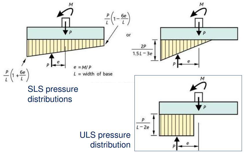
(a) Design ultimate bearing pressure
For a concentrically loaded pad foundation, the design earth pressure is given by;
q = P/Aprov
Where;
P = Design axial force of the column = 1.35Gk + 1.5Qk (kN)
Aprov = Base area provided for the footing (m2)
(b)
(b) Bending
The critical section for bending is at the face of the column on a pad footing or the wall in a strip footing. The moment is taken on a section passing completely across a pad footing and is due to the ultimate loads on one side of the section. No redistribution of moments should be made.
(c) Beam Shear
The vertical shear force is the sum of the loads acting outside the section considered. Shear stress is checked at a distance d from the face of the column. It is normal practice to make the base sufficiently deep so that shear reinforcement is not required. The depth of the base is often controlled by the design for shear.
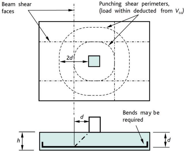
(d) Punching Shear
Rules for checking for punching shear resistance are given in section 6.4 of EN 1992-1-1:2004. The punching shear force is the sum of the loads outside the periphery of the critical section. Two punching shear checks should be carried out – at the column perimeter and at between d – 2d from the face of the column.
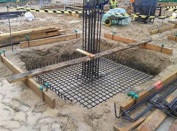
Structural Design Example of Pad Foundation
Design a square pad footing for a 250 × 250 mm column carrying a characteristic permanent load Gk of 800 kN and characteristic variable load Qk of 425 kN. The presumed allowable bearing pressure of the non-aggressive soil is 225 kN/m2. fck = 30 N/mm2; fyk = 500 N/mm2; Concrete cover = 50 mm
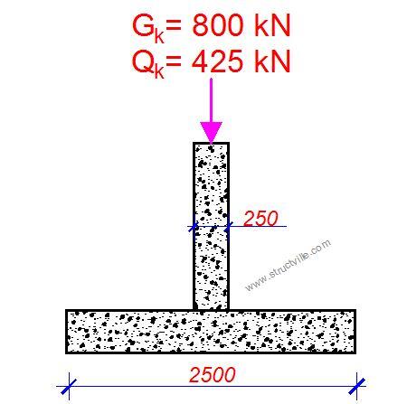
Pad foundation is a category 2 structure, and this design is to be done using prescriptive methods:
Let 10% of the service load account for the self-weight of the pad foundation.
Base area A = 1.1(800 + 425)/225 = 5.99 m2
Minimum dimensions of footing = √5.99 = 2.447m
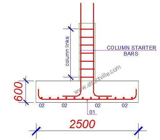
Adopt a square foundation of 2500 mm x 2500m x (600 mm) trial depth (Area provided Aprov = 6.25 m2)
Loading at ultimate limit state NEd = (1.35 x 800) + (1.5 x 425) = 1717.5 kN
ULS bearing pressure NEd/Aprov = 1717.5/6.25 = 274.8 kN/m2
Critical design moment at the face of the column
MEd = (274.8 x 1.1252)/2 = 173.89 kNm/m
Effective depth d = 600 – 50 – 16 = 534 mm
k = MEd/(bd2fck) = (173.89 x 10⁶)/(100 x 5342 x 30) = 0.0203
⇒ z = 0.95d = 0.95 x 534 = 507.3 mm
⇒ As = MEd/0.87fykz = (173.89 x 10⁶)/(0.87 x 500 x 507.3) = 788 mm2/m
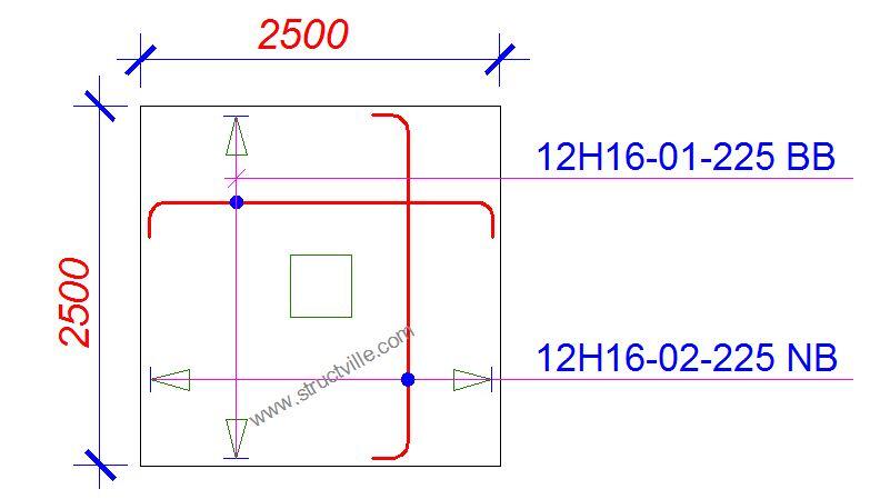
Provide H16 @ 225 c/c both ways (Asprov = 893 mm2/m)
Beam shear
Check critical section d away from column face
VEd = 274.8 x (1.125 – 0.534) = 162.4 kN/m
vEd = 162.4/534 = 0.304 N/mm2
vRd, c = CRd, c × k × (100 × ρ1 × fck) 0.3333
CRd, c = 0.12
k = 1 + √ (200/d) = 1 + √ (200/534) = 1.611
ρ = 893/(534 × 1000) = 0.00167
vRd, c = 0.12 × 1.611 × (100 × 0.00167 × 30)0.333 = 0.33 N/mm2
=> vEd (0.304 N/mm2) < vRd,c (0.33 N/mm2) beam shear ok
Punching Shear
Punching shear: Basic control perimeter at 2d from face of column
vEd = βVEd/uid < vRd,c
β = 1,
ui = (250 x 4 + 534 x 2 x 2 x π) = 7710 mm
VEd = load minus net upward force within the area of the control perimeter)
VEd = 1717.5 – 274.8 x (0.252 + π x 1.0682 + 1.068 x 0.25 x 4) = 422 kN
vEd = (422 x 103)/(7710 x 534) = 0.102 N/mm2
Punching shear is therefore okay
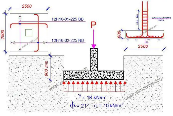
Detailing sketches of pad foundation





Thanks for the design info
Sharp and excellent
Thank you Sir.I saw this info just at the right time.Please Clarify on the units of the critical design moment(Med) that was (kNm/m).? Instead of kNm as a moment.
Thank you Sir
The design was done was done per unit strip of the base, hence kNm/m instead of kNm
Good one. God bless you Engr Ubani
Its very elaborate
Thank you Eng.Ubani
Very comphrensive. thanks
very comprehensive
thanks!
Can you please confirm the Overburden Factor in your example and the value of eccentricity e?
EXCELLENT WORK, WHILE TEXTBOOKS WERE BEATING AROUNDN THE BUSH, YOU WENT STRAIGHT TO THE POINT. THANKS EHGR RANKS.
good job
Hello, well-done for the good work you are doing. Please can you check the Moment, Med you obtained?. Multiplying the earth pressure by an 1.125^2 gives force in N and not moment in KNm.
You may wish to multiply the value by the 2.5 which is the size( the side since the pad is square pad) to give us a moment for which other calculation can proceed.
Thank you sir ?
Dear Engr, You are doing a good Job.
I wish to draw your attention to a small issue on the structural design of PAD you presented above. The moment here did not take account of the length of the pad(2.5m). I mean Med should also add as a multiple 2.5m so as to get the moment in KNm.
see Med=274.8 x 1.125^2/2= 173.8KNm.
Thank you and well-done
Hi mate,
This moment should be in kNm/m (i.e., kNm per metre width of the footing).
Hope this clear your confusion.
Cheers
May God bless you sir
Thank You, its good paper
Dear Engr,
Believe in yourself.
Pls, Engr. What’s taper height in foundation design
Pls, ENGR. I am finding difficulties on how to label my pad foundation base after calculating the axial load and moment on the axis
Great content , I would appreciate if you can publish analysis and design of tower foundation with inverted frustum
Thanks
Great content , I would appreciate if you can publish analysis and design of tower foundation(electrical transmission tower like monopole) with inverted frustum
Thanks