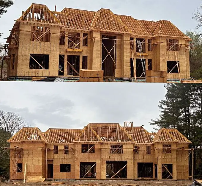
Timber framed buildings are buildings whose structural members such as beams, columns, decking, and roofs are constructed using natural or engineered wood/timber materials. Among other construction materials such as steel and concrete, timber is distinguished by its comparatively low weight and superior carbon footprint.
The low-weight characteristic of timber framed buildings translates to several advantages in construction such as ease of handling during construction and reduced dead load of the structure. This means cheaper labour during erection and cheaper foundation costs for the building.

Furthermore, timber exhibits a favourable strength-to-weight ratio, signifying its ability to bear significant loads relative to its mass. Additionally, it possesses adequate stiffness in proportion to its strength, which enhances its structural stability.
The distribution of buildings constructed with timber varies across the world. There is a lot of encouragement for the adoption of wood as a construction material, especially due to its environmental friendliness compared to concrete and steel. Recently across the world, modern tall buildings and bridges are being constructed using timber.
Norway currently holds the record of constructing the world’s tallest timber building, Mjøstårnet, a mixed-use tower designed by Voll Arkitekter and built by Hent and Moelven Limtre. This impressive structure, reaching 85.4 meters in height, utilizes a glue-laminated timber (glulam) frame with CLT wall panels for secondary load-bearing purposes.
The modern uses of timber in the construction industry extend beyond high-rise construction. Australia, for instance, predominantly utilizes lightweight framing in its construction practices, with timber and steel being the favoured materials. Notably, timber offers a significant environmental advantage.
When compared to sawn timber, steel, concrete, and aluminium, timber demonstrably releases the least amount of carbon during construction. Additionally, timber stands out as the sole building material that actively stores carbon.
New Zealand mirrors Australia’s preference for timber construction, with timber frame construction dominating residential projects. Timber framing for residential buildings boasts a dominant market share of approximately 90% compared to alternative framing methods such as steel, masonry, or concrete.

France has taken a bold step towards promoting sustainable building practices. In 2021, the French government mandated that all new public buildings must incorporate at least 50% timber or other natural materials in their construction, with implementation commencing in 2022.
This global overview underscores the burgeoning interest in timber construction and its potential to contribute to a more sustainable built environment. From record-breaking high-rises to widespread residential applications, timber is proving to be a versatile and environmentally friendly construction material. As innovation continues and regulations evolve, the future of timber construction appears bright.
Demand and Supply of Wood for Building Construction
The availability of wood for timber construction varies significantly across the globe, influenced by factors like forest cover, harvesting practices, and economic development. The United States, Canada, and Mexico boast vast coniferous (softwood) forests, making them major timber producers. In Europe, countries like Sweden, Finland, and Norway also have extensive coniferous forests and well-developed forest management systems, ensuring a steady supply of high-quality timber for construction.
According to the UK government, the UK is the third largest importer of timber and timber products in the world. However, by leveraging robust quality control procedures and streamlined industrial manufacturing processes, the high cost associated with imported timber in some countries can be effectively mitigated by factory prefabrication of complete wall, floor, and roof units.
This prefabrication approach leads to further advantages on the construction site. The use of mobile cranes and semi-skilled labour for a streamlined assembly process affords a significant reduction in overall construction time. The process of prefabricating structural units in timber eliminates the dependency on highly skilled carpentry on-site. This approach streamlines the construction process, as all joints can be efficiently secured using nails.

While the cost of timber in some countries might be considered a disadvantage, it is essential to acknowledge other aspects:
- Fire Resistance: Timber with smaller dimensions (less than 150mm x 100mm) exhibits limited fire resistance due to the insufficient material volume for charring, which would otherwise protect the inner structure. This limitation can be effectively addressed by employing non-combustible cladding materials, such as internal plasterboard and external facing brick.
- Hygroscopic Nature: Timber is hygroscopic nature, which means it readily absorbs and releases moisture. This can contribute to decay in environments with high humidity. However, this concern can be mitigated through proper moisture management strategies during construction.
Techniques such as installing the timber in a dry state, incorporating damp-proof courses (DPCs), and utilizing vapour control layers can significantly reduce the risk of dampness penetration and subsequent decay.
Sustainability of Timber Buildings
When it comes to sustainability in construction, timber performs better compared to concrete and steel. Timber is a renewable resource, with sustainably managed forests ensuring its continued availability. During its growth, timber acts as a carbon sink, actively sequestering carbon dioxide from the atmosphere.
This carbon storage remains trapped within the wood even after it’s harvested for construction, offering a significant embodied carbon benefit over concrete and steel, which both produce substantial carbon emissions during their manufacturing processes. Furthermore, the use of timber often translates to less energy-intensive construction methods, like prefabrication, further reducing the overall environmental footprint of timber-framed buildings.
However, sustainable timber practices are important. Sourcing timber from certified forests that prioritize responsible harvesting and reforestation is essential to maintain the environmental benefits. Additionally, proper treatment and protection of timber during construction and throughout the building’s lifespan are necessary to ensure its durability and minimize the need for replacements, which would negate the initial carbon sequestration advantage.
In essence, the core of a timber-framed building is the frame itself, typically constructed from seasoned, high-quality lumber. Here’s a breakdown of the key components:
- Posts/columns: These vertical members carry the main weight of the structure, transferring loads from the roof to the foundation. Sizes vary depending on the building design and load requirements.
- Beams: These horizontal members span between posts, supporting the floor and roof loads. Beam sizes are determined by the span length and intended load.
- Braces: Diagonal members provide lateral stability to the frame, resisting wind and seismic loads. Bracing can be installed in various configurations, such as X-braces or knee braces.
- Lintels: These horizontal members are placed above openings like windows and doors to support the wall loads above the opening.
- Connectors: Metal connectors, such as plates, brackets, and nails, are used to join timber members securely, creating a rigid and stable frame.

Timber Frame Construction
There are two distinct forms of timber frame:
- Balloon
- Platform
Both configurations are constructed upon a foundation consisting of either masonry or concrete walls. The selection for the ground floor can be either a suspended timber floor or a solid concrete slab.
For suspended timber floors, as illustrated below, both balloon and platform styles commence with a “ring beam” built upon a wall plate. The ring beam and wall plate are then securely fastened to the underlying masonry base using rag bolts. This ring beam can be comprised of either a singular timber or two timbers joined by nails.

Solid concrete floors, as detailed below, offer two potential foundation options. The first option utilizes a separate floor slab constructed upon a masonry wall. The second option employs a single-poured concrete structure that incorporates the foundation, wall, and floor slab into a single element.

As prevalent in the United States of America and Canada, poured concrete walls can be utilized to create basements or semi-basements. This approach eliminates the need for a timber ring beam. Instead, the wall plate is securely fastened using rag bolts directly to the edge of the concrete floor slab.

In traditional timber ring beam construction, a sole plate comprised of two timbers laid flat was typically installed. Conversely, when employing a wall plate on a concrete floor edge, a single-layer sole plate is enough. Regardless of the method, vertical studs were then erected, with their height determined by the chosen construction style (balloon or platform).
Platform construction involves utilizing studs measuring one story in height. Floor joists are positioned atop these studs to create a platform. Subsequently, another sole plate is installed, followed by additional studs for the next story.
Balloon framing, in contrast, utilizes studs spanning two stories. Acquiring timbers of sufficient length for exceeding two stories is generally impractical. The intermediate floor is then connected to the midpoint of the studs.

Both approaches incorporate a degree of prefabrication, typically performed on-site. This process usually involves securing studs to a single layer of the sole plate for a complete wall section.

The studs are then capped with a single runner, all assembled on the ground or floor slab. Bracing elements, constructed from thin, wide timber, are slotted into recesses formed within the sole plate, studs, and runners. Additionally, dwangs are incorporated at approximately 750 mm intervals along the stud height.
Finally, the completed frame section is erected on the wall plate or the remaining half of the sole plate. These two components are then joined with nails, and temporary bracing ensures the panel remains upright. A double runner is then installed atop the assembled panels.

Platform framing utilizes a double runner positioned atop the studs to serve as a bearing point for the upper floor joists. Following their installation, another single sole plate is secured using nails to the top of the joists. This sole plate then serves as the foundation for an additional set of wall panels corresponding to the next storey height. This process is repeated sequentially. A final double runner is installed atop the uppermost set of panels, and the roof timbers are affixed to this double runner.
In contrast, balloon framing employs a different approach for supporting the floor joining at the midpoint of the stud length. Here, support is achieved through a combination of a thin, wide timber member known as a riband, which is inserted into a recess within the inner face of the stud, and a halving joint created between the joist and stud, further secured with nails driven into the stud. The topmost section of the framed panel is constructed using a single runner. If the roof requires attachment at this level, the runner is doubled, mirroring the approach used in platform framing.
A critical aspect of both platform and balloon construction methods is ensuring consistent spacing for all timbers (joists, studs, and roof timbers). This uniformity allows for the efficient transfer of loads originating from the roof and upper floors directly down to the studs through the joist ends.
For reference, here are the typical dimensions for the various timber components used in this construction method:
- Studs, runners, sole and wall plates, dwangs, and noggings: 150mm x 50mm to 200mm x 75 mm
- Bracing and ribands: generally 32 or 38 mm thick and 200 to 250 mm wide
- Joists: 150 x 50 mm to 300 x 75 mm
- Diagonal boarding: 20 or 25 mm thick, 150 or 200 mm wide
- Clap boarding and weatherboarding: 15 or 20 mm thick
- Matchboarding: 15 mm thick
Following the erection of the frame, the exterior surface is covered with plain-edged sawn boards, typically measuring 150 to 200 mm wide and 20 to 25 mm thick. These boards are laid diagonally with their edges butted together tightly and secured using two nails driven through their face and into each underlying timber element (studs, sole plates, runners, and dwangs).

Construction of Timber Suspended Upper Floors
A suspended timber upper floor is comprised of a network of beams, technically known as joists. These joists are supported by load-bearing walls or header timber beams and are specifically sized and spaced to ensure they can safely bear all anticipated static (dead) and variable (imposed) loads placed upon the floor.

A suspended timber upper floor serves several important purposes within a building structure:
- Structural Integrity: The primary function is to provide a level and robust platform capable of safely sustaining imposed loads from occupants, furniture, and equipment. This also includes the dead weight of the floor itself and any ceiling structure suspended below.
- Thermal Efficiency: The floor plays a role in minimizing heat loss from the lower floor. The specific level of thermal resistance is determined by design considerations and may involve the use of insulation materials within the floor cavity.
- Acoustic Performance: The floor assembly contributes to sound insulation, mitigating the transmission of noise between floors. The specific level of soundproofing achieved depends on the design and materials employed.
- Fire Safety: The floor contributes to the building’s overall fire resistance, potentially slowing the spread of flames and providing additional time for evacuation in the event of a fire. The specific level of fire resistance is determined by the type of timber used, any fire-retardant treatments applied, and the overall floor assembly design.
Selection of Timber Joist Sizes
Timber joist sizes can be selected using the following methods;
(1) Full structural design of the timber joists
(2) Selection from span-load tables
(3) Empirical formula (Depth of joist = [Span (mm)/24 + 50]; where the assumed width and spacing of the joists are 50 mm and 400 mm c/c respectively).
A typical span-load table for the general structural grade (GS) timber joist is shown below.

While span-load tables and formulas offer valuable tools for specifying timber elements in construction, it’s acknowledged that they possess limitations. In situations where loads, spans, or joist spacings fall outside the parameters encompassed by these tables, more rigorous calculations become necessary.
Simply calculating the overall dimensions of a timber element is not sufficient for ensuring its structural adequacy. Additional checks are important to confirm that the element meets essential performance criteria:
- Deflection Resistance: The element must possess adequate stiffness to limit deflection under applied loads. Excessive deflection can lead to serviceability issues, such as cracking of finishes or creating an uncomfortable walking surface.
- Safe Bearing Capacity: The element’s bearing area where it rests on supports must be sufficient to prevent crushing of the timber or failure of the supporting structure.
- Shear Resistance: The element must be able to withstand internal shearing forces that act parallel to the grain of the wood. Failure in shear can lead to a sudden and catastrophic collapse.
For such scenarios, this article recommends consulting two informative resources:
- BS EN 1995-1-1: Design of timber structures: This European Standard provides comprehensive guidance on the design of timber structures.
- BS EN 338: Structural timber strength classes: This European Standard focuses on structural timber and incorporates information regarding the strength classes of various timber species.
By consulting these resources, engineers can obtain the necessary data to perform the required calculations and ensure the safe and appropriate use of timber in situations exceeding the scope of design tables.
Strutting (Blocking) of Timber Floor Joists
In suspended timber floor construction, strutting elements are incorporated to limit the potential twisting and vibration of the floor joists. These movements, if left unchecked, could lead to damage to the ceiling finishes. Strutting is typically employed when the span of the joists surpasses 2.5 m. Ideally, the strutting should be positioned at the centre line of the joist span.

It’s important to note that the maximum achievable span for a floor joist, measured centre-to-centre between bearing points (including the centre line of the inner leaf in a cavity wall), is approximately 6 m.
To ensure stability, external walls (including compartment walls, separating walls, and party walls), as well as internal load-bearing walls, must be provided with lateral restraints from adjacent floor structures. This serves to restrict lateral movement of the walls. Exceptions to this requirement exist for walls with a length of less than 3 meters.

Methods for achieving lateral restraint
| Method | Description |
|---|---|
| End Bearing of Floor Joists | Floor joists should bear on the wall for a minimum of 90 mm and be spaced at intervals not exceeding 1.2m. |
| Galvanized Steel Straps | Alternatively, galvanized steel straps can be employed. These straps should be spaced at intervals not exceeding 2 m and securely fastened perpendicular to the joists. |
Services Installation and Maintenance
It is important to conceal pipes and cables within a building structure while maintaining accessibility for future maintenance and repairs. When employing timber joists, there are strategic placement options for these service elements. Pipes and cables running parallel to the joists can be conveniently secured to their sides. However, running them perpendicular to the joists necessitates creating holes or notches within the timber itself.
The creation of holes within timber joists is suitable for accommodating flexible cables and coiled soft copper microbore tubing. The ideal location for these holes in simply supported, end-bearing floor joists is at the neutral axis. This specific zone represents the point where compressive and tensile load distribution neutralize, and the material experiences minimal dimensional change (neither lengthening nor shortening) under deflection.

To protect the structural integrity of timber joists, limitations are placed on the size, spacing, and location of any holes created within them.
- Maximum Diameter: The diameter of a hole cannot exceed 25% of the joist’s depth.
- Minimum Spacing: Multiple holes necessitate a minimum center-to-center spacing equivalent to three times the diameter of each hole.
- Ideal Location: The preferred location for a hole is within the neutral axis of the joist. This zone lies between 25% and 40% of the clear span, measured from the support point where the joist rests. The neutral axis represents the area within the joist that experiences minimal stress from bending forces.
Notches are the most practical method for incorporating rigid pipes and conduits into floors constructed with joists. However, to minimize the impact on the joist’s structural integrity, specific restrictions govern the depth and placement of these notches.
- Maximum Depth: The depth of a notch cannot exceed 12.5% of the joist’s depth.
- Permissible Location: Notches can only be made within a designated zone ranging from 7% to 25% of the clear span, measured from the support where the joist rests. This ensures that the notch is located in an area experiencing minimal bending stress.
Fire Protection of Timber Floors
This section outlines fire resistance classifications for floors based on their relative height from the surrounding ground:
- Less than 5 meters: Floors situated less than 5 meters above the adjacent ground require a minimum fire resistance rating of 30 minutes.
- More than 5 meters: Floors exceeding 5 meters in height necessitate a minimum fire resistance rating of 60 minutes. However, a 30-minute rating is considered sufficient for three-story dwellings in this category.

These fire resistance ratings are determined through testing procedures outlined in BS 476 Part 21: Fire tests on building materials and structures. Methods for determination of the fire resistance of load bearing elements of construction. This standard evaluates three key aspects of an element’s fire performance:
- Load-Bearing Capacity: The ability of the element to sustain its structural integrity during a fire event.
- Integrity: The element’s capacity to resist fire penetration and prevent the spread of flames.
- Insulation: The element’s ability to impede heat transfer through radiation and conduction, thereby slowing the spread of fire.
It is important to note that floors constructed over basements or garages must possess a full 30 minutes of fire resistance. Furthermore, when a floor provides structural support or stability for a wall (or vice versa), the fire resistance rating of the supporting element must be equal to or greater than the fire resistance rating of the other element. This ensures a consistent level of fire protection within the building structure.

