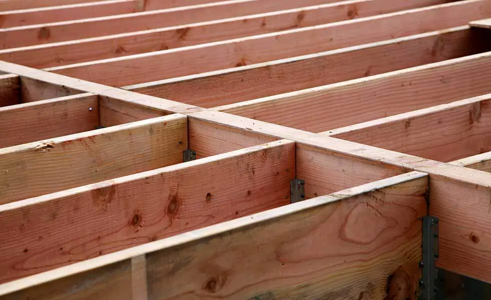
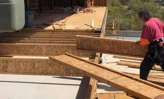
Timber joists are flexural horizontal timber members that are used for framing an open space in a building in order to support a floor or sheathing. They are usually closely spaced (usually between 400 – 800 mm) with the plane of maximum strength positioned vertically.
The spans of the joists are usually supported or intercepted by blockings which may be linear or skewed (staggered). Timber joists transfer the load of the floor to the vertical compression members (such as timber columns) and can be made of solid timber, glulam, or other engineered wood products.
As flexural structural members, the design of timber joists is expected to satisfy the following requirements;
- Bending
- Shear
- Bearing
- Lateral buckling
- Deflection, and
- Vibration
Design Example of Timber Joists
In this article, let us design the timber floor joists for a domestic dwelling using timber of strength class C24 to support a medium-term permanent action of 0.75 kN/m2 and a variable (live) load of 1.5 kN/m2 given that the:
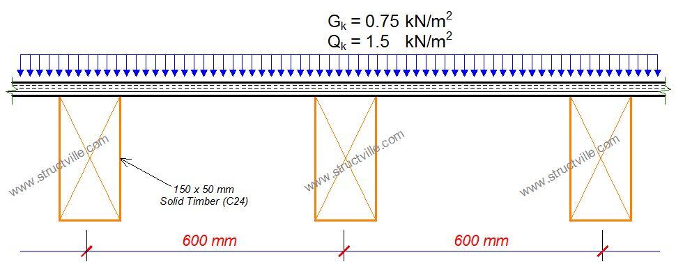
a) floor width, b, is 3.6 m and floor span, l, is 3.0 m
b) joists are spaced at 600 mm centres
c) the bearing length is 100 mm

Self weight of timber = 3.4335 kN/m3 x 0.15m x 0.05m = 0.0257 kN/m
Chaaracteristic permaent action on each joist = 0.75 kN/m2 x 0.6m = 0.45 kN/m
Total characteristic permanent action gk = 0.476 kN/m
Total characteristic variable action qk = 1.5 kN/m2 x 0.6 m = 0.9 kN/m
At ultimate state; pEd = 1.35gk + 1.5qk = 1.9926 kN/m
At serviceability limit state pEd = 1.0gk + 1.0qk = 1.376 kN/m
Structural Analysis

Structural Design
Member – Span 1
The partial factor for material properties and resistances
Partial factor for material properties (Table 2.3 of EN 1995-1-1:2004); γM = 1.300
Member details
Load duration (cl.2.3.1.2 of EC5); Medium-term
Service class – (cl.2.3.1.3 of EC5); 2
Timber section details
Number of timber sections in member; N = 1
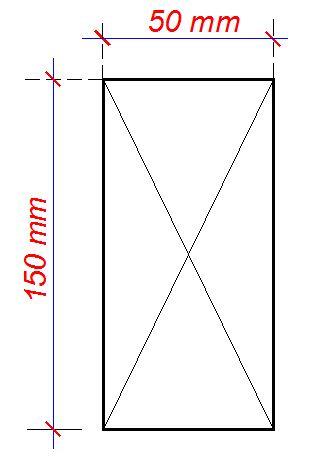
Breadth of sections; b = 50 mm
Depth of sections; h = 150 mm
Timber strength class – EN 338:2016 Table 1; C24
Properties of 50 x 150 mm timber section
Cross-sectional area, A = 7500 mm2
Section modulus, Wy = 187500 mm3
Section modulus, Wz = 62500 mm3
Second moment of area, Iy = 14062500 mm4
Second moment of area, Iz = 1562500 mm4
Radius of gyration, iy = 43.3 mm
Radius of gyration, iz = 14.4 mm
Timber strength class C24
Characteristic bending strength, fm.k = 24 N/mm2
Characteristic shear strength, fv.k = 4 N/mm2
Characteristic compression strength parallel to grain, fc.0.k = 21 N/mm2
Characteristic compression strength perpendicular to grain, fc.90.k = 2.5 N/mm2
Characteristic tension strength parallel to grain, ft.0.k = 14.5 N/mm2
Mean modulus of elasticity, E0.mean = 11000 N/mm2
Fifth percentile modulus of elasticity, E0.05 = 7400 N/mm2
Shear modulus of elasticity, Gmean = 690 N/mm2
Characteristic density, rk = 350 kg/m3
Mean density, rmean = 420 kg/m3
Consider Combination 1 – 1.35Gk + 1.5Qk (Strength)
Modification factors
Duration of load and moisture content – Table 3.1; kmod = 0.8
Deformation factor – Table 3.2; kdef = 0.8
Bending stress re-distribution factor – cl.6.1.6(2); km = 0.7
Crack factor for shear resistance – cl.6.1.7(2); kcr = 0.67
Load configuration factor – cl.6.1.5(4); kc,90 = 1.5
System strength factor – cl.6.6; ksys = 1.1
At the start of span
Check compression perpendicular to the grain (cl.6.1.5 of EC5)
Design perpendicular compression – major axis; Fc,y,90,d = 2.394 kN
Effective contact length; Lb,ef = Lb = 100 mm
Design perpendicular compressive stress – exp.6.4; sc,y,90,d = Fc,y,90,d / (b × Lb,ef) = 0.479 N/mm2
Design perpendicular compressive strength; fc,y,90,d = kmod × ksys × fc.90.k / γM = 1.692 N/mm2
sc,y,90,d / (kc,90 × fc,y,90,d) = 0.189
PASS – Design perpendicular compression strength exceeds design perpendicular compression stress
Check shear force (Section 6.1.7 of EC5)
Design shear force; Fy,d = 2.394 kN
Design shear stress – exp.6.60; ty,d = 1.5 × Fy,d / (kcr × b × h) = 0.714 N/mm2
Design shear strength; fv,y,d = kmod × ksys × fv.k / γM = 2.708 N/mm2
ty,d / fv,y,d = 0.264
PASS – Design shear strength exceeds design shear stress
At the end of span
Check compression perpendicular to the grain – cl.6.1.5
Design perpendicular compression – major axis; Fc,y,90,d = 6.572 kN
Effective contact length; Lb,ef = Lb = 100 mm
Design perpendicular compressive stress – exp.6.4;
sc,y,90,d = Fc,y,90,d / (b × Lb,ef) = 1.314 N/mm2
Design perpendicular compressive strength;
fc,y,90,d = kmod × ksys × fc.90.k / γM = 1.692 N/mm2
sc,y,90,d / (kc,90 fc,y,90,d) = 0.518
PASS – Design perpendicular compression strength exceeds design perpendicular compression stress
Check shear force – Section 6.1.7
Design shear force; Fy,d = 3.583 kN
Design shear stress – exp.6.60; ty,d = 1.5 × Fy,d / (kcr × b × h) = 1.070 N/mm2
Design shear strength; fv,y,d = kmod × ksys × fv.k / γM = 2.708 N/mm2
ty,d / fv,y,d = 0.395
PASS – Design shear strength exceeds design shear stress
Check bending moment – Section 6.1.6
Design bending moment; My,d = 1.784 kNm
Design bending stress; sm,y,d = My,d / Wy = 9.517 N/mm2
Design bending strength; fm,y,d = kmod × ksys × fm.k / γM = 16.246 N/mm2
sm,y,d / fm,y,d = 0.586
PASS – Design bending strength exceeds design bending stress
Serviceability Limit State
Consider Combination 2 – 1.0Gk + 1.0Qk (Service)
Check y-y axis deflection – Section 7.2
Instantaneous deflection; dy = 5.3 mm
Quasi-permanent variable load factor; y2 = 0.3
Final deflection with creep; dy,Final = 0.5 × dy × (1 + kdef) + 0.5 × dy × (1 + y2 × kdef) = 8.1 mm
Allowable deflection; dy,Allowable = L / 250 = 12 mm
dy,Final / dy,Allowable = 0.676
Therefore, the final deflection is acceptable.
It is also typical to check the floor for vibration, but this was not considered in this design.








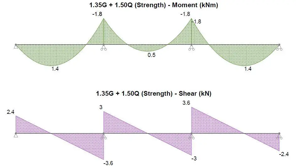
Hello. I was going through this and its great work. But i am not understanding how you are able to get the design perpendicular compression at the start of the span and at the end as 2.394 and 6.572.where did you calculate them from
Hi Brian, take a look at the shear force diagram, the support reaction at the start of the span is 2.394 kN (approximated as 2.4 kN, while the total support reaction at the penultimate support is approximately 6.6 kN (3 + 3.6 = 6.6 kN).