Design of flexural members such as timber beams principally involves consideration of the effects of actions such as bending, deflection, vibration, lateral buckling, shear, and bearing. The process of design of such structures is described in Eurocode 5 (EN 1995-1-1:2004), and a design example is shown in this article.
Design Example
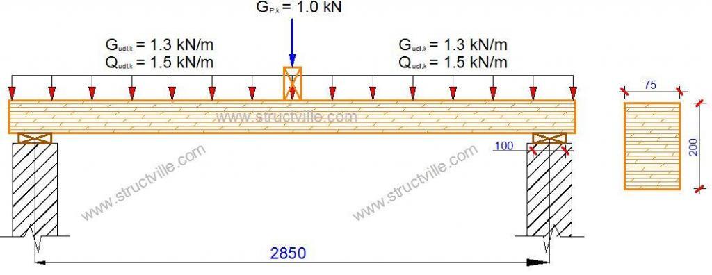
A 75 mm by 200 mm deep sawn timber beam in a domestic residence supports the characteristic loading shown above. The beam has a clear span of 2.75 m, the bearing length has been restricted to 100 mm at each end, is of strength class C24 to BS EN 338:2003, and functions in service class 2 conditions. The beam is laterally restrained against lateral buckling along its length.
Given that;
Gk.udl = 1.3 kN/m (characteristic uniformly distributed permanent action)
Qk.udl = 1.5 kN/m (characteristic uniformly distributed medium-term action)
Gk.p = 1.00 kN characteristic point load at mid-span
1. Beam geometric properties
Breadth of the beam b = 75 mm
Depth of the beam h = 200 mm
Clear span of the beam, lc = 2750 mm
Bearing length of the beam at each end, bl = 100 mm
Design span of the beam l = (lc + lb) = 2750 + 100 = 2850 = 2.85 m
Section modulus of the beam about the y–y axis, Wy = bh2/6 = (75 × 2002)/6 = 5 × 105 mm3
2. Timber properties
Strength class C24 (BS EN 338:2003, Table 1):
Characteristic bending strength, fm.k = 24 N/mm2
Characteristic shear strength, fv.k = 2.5 N/mm2
Characteristic bearing strength, fc,90,k = 2.5 N/mm2
Fifth-percentile modulus of elasticity parallel to the grain, E0.05 = 7.4 kN/mm2
Mean modulus of elasticity parallel to the grain, E0,mean = 11 kN/mm2
Mean shear modulus, G0,mean = 0.69 kN/mm2
Mean density of the beam timber, ρm = 420 kg/m3
3. Partial safety factors
(UKNA to BS EN 1990:2002, Table NA.A1.2(B))) for the ULS
Permanent actions, γG.ULS = 1.35
Variable actions, γQ.ULS = 1.5
(UKNA to BS EN 1990:2002, Table NA.A1.1 – Category A)
Factor for the quasi-permanent value of the variable action, ψ2 = 0.3
(UKNA to EC5, Table NA.3)
Material factor for solid timber at the ULS, γM = 1.3
4. Actions
(i) ULS
(a) Characteristic self-weight of the beam, Gk,swt
Gk,swt = b · h · g · ρm = (0.075 × 0.2 × 9.81 × 420)/1000 = 0.062 kN/m
Design action from the selfweight of the beam, Fd,swt
Fd,swt = γG.ULS · Gk.swt = 1.35 × 0.062 = 0.0837 kN/m
(b) Characteristic permanent action due to the point load, Gk,p
Gk,p = 1.00 kN
Design permanent action due to the point load, Fd.p
Fd,p = γG.ULS · Gk.p = 1.35 × 1.0 = 1.35 kN
(c) Characteristic permanent action due to the UDL, Gk,udl
Gk,udl = 1.3 kN/m
Design action due to the permanent action UDL, Fd,p,udl
Fd,p,udl = γG.ULS · Gk.udl =1.35 x 1.3 = 1.755 kN/m
(d) Characteristic medium-term action due to the UDL, Qk,udl
Qk,udl = 1.5 kN/m
Design action due to the variable action UDL, Fd,q,udl
Fd,q,udl = γQ.ULS · Qk.udl = 1.5 × 1.5 = 2.25 kN/m
Total UDL @ ULS = 0.0837 + 1.755 + 2.25 = 4.1 kN/m
Total concentrated action @ ULS = 1.35 kN
5. Modification factors
Factor for medium-duration loading and service class 2, kmod.med = 0.8 (EC5, Table 3.1)
Size factor for depth greater than 150 mm, kh = 1.0 (EC5, equation (3.1))
Lateral stability of the beam: kcrit = 1 (EC5, 6.3.3))
Bearing factor kc,90 = (taken as 1.0) (EC5, clause 6.1.5(2) )
Deformation factor for service class 2, kdef = 0.8 (EC5, Table 3.2)
Load sharing factor, ksys is not relevant ksys = 1.0
(6) Bending strength
The design bending moment;
Md =ql2/8 + PL/4= (4.1 × 2.852)/8 + (1.35 × 2.85)/4 = 4.162 + 0.96 = 5.122 kNm
Design bending stress, σm,y,d = Md/Wy = (5.122 × 10⁶)/( 5 × 10⁵) = 10.244 N/mm2
Design bending strength, fm,y,d = (kmod.med·ksys·kh· fm.k)/γM = (0.8 × 1.0 × 1.0 × 24)/1.3 = 14.77 N/mm2
σm,y,d < fm,y,d Section is okay in bending
(7) Shear Strength
Design shear force Vd = ql/2 + P/2 = (4.1 × 2.85)/2 + (1.35/2) = 6.52 kN
Design shear stress, τv.d (EC5, equation (6.60))
τv.d = 1.5Vd/bhef = (1.5 × 6.52 × 1000)/(75 × 200) = 0.652 N/mm2
Design shear strength, fv,d = (kmod.med·ksys· fv.k)/γM = (0.8 × 1.0 × 2.5)/1.3 = 1.54 N/mm2
τv.d < fv,d Section is okay in shear
(8) Bearing Strength
The design bearing force will equal the design shear force in the beam, Vd
Design bearing stress, σc,90,d = Vd/b·lb = (6.52 × 1000)/(75 x 100) = 0.833 N/mm2
Design bearing strength, (EC5,equation (6.3)))
fc.90.d = (kmod.med · ksys · kc.90 · fc.90.k)/ γM = (0.8 × 1.0 × 2.5)/1.3 = 1.54 N/mm2
σc,90,d < fc.90.d Section is okay in bearing
(9) Deflection
Instantaneous deflection due to permanent actions

uinst,point,G = (1/4) × [1/(11 × 75 × 2003)] × 28503 × [1 + 1.2 × (11/0.69) × (200/2850)2] = 0.959 mm
Uinst,udl,G = (5/32) × [(1.3 × 10⁻³ + 0.062 × 10⁻³)/(11 × 75 × 2003)] × 28504 × [1 + 0.96 × (11/0.69) × (200/2850)2] = 2.287 mm
Uinst.G = uinst,point,G + Uinst,udl,G = 0.959 + 2.287 = 3.246 mm
Instantaneous deflection due to variable action

Uinst,Q = (5/32) × [(1.5 × 10⁻³)/(11 × 75 × 2003)] × 28504 × [1 + 0.96 × (11/0.69) × (200/2850)2] = 2.519 mm
Combined permanent and variable instantaneous deflection = uinst = uinst,G + uinst,Q = 3.246 + 2.519 = 5.765 mm
Eurocode 5 limit on deflection (Table 7.2, EC5) winst = l/300 = 2850/300 = 9.5 mm (uinst < winst Instantaneous deflection is okay)
Final deflection
Final deflection due to permanent actions ufin,G = uinst,G (1 + kdef) (Equation 2.3, EC5)
ufin,G = 3.246 (1 + 0.8) = 5.843 mm
Final deflection due to the variable and quasi-permanent actions, ufin,Q = uinst,Q (1 + ψ2kdef) (Equation 2.4, EC5)
ufin,Q = uinst,Q (1 + ψ2kdef) = 2.519 (1 + 0.3 × 0.8 ) = 3.12 mm
Final deflection due to the permanent and quasi-permanent actions actions
unet,fin = ufin,G + ufin,Q = 5.843 + 3.12 = 8.963 mm
Deflection limit wnet,fin = l/150 = 2850/150 = 19 mm
The deflection of the beam is satisfactory
To download this design article in PDF format, click HERE.





good work, keep the work flying.