Axially loaded timber members are usually employed in building construction. Sometimes, these members are also subjected to simultaneous axial compression and bending. Some of these members include timber columns or beams, truss members, vertical wall studs, and bracing components. The design of timber columns involves the selection of adequate timber grade and section that will safely carry the anticipated load without undergoing excessive deflection or failure by squashing, buckling, or shear.
The limit states associated with the primary design effects for axially loaded members must also comply with the pertinent design rules and requirements of EN 1995-1-1:2004 (EC5). The equilibrium states and strength conditions are ultimate limit states because they are related to failure scenarios. The displacement condition pertains to situations encountered in typical usage, but EC5 offers no guidance on the state’s limiting criteria.

Where lateral instability of a member may occur, Section 10 of EN 1995-1-1 sets limitations on the maximum permissible deviation from straightness. For strength-related conditions, the design stress is calculated and compared with the design strength, which is modified as necessary by strength factors. When using the partial factor technique, the design stress cannot be greater than the design strength in order to comply with code reliability requirements.
When members or structures are subjected to combined stresses, such as those caused by the combined effects of axial and bending actions, extra design effects will need to be considered.
In this article, we are going to present an example of how we can design axially loaded timber columns according to the requirements of Eurocode 5.
Timber Columns Subjected to Axial Compression
These are members that are subjected to a compressive axial force acting perpendicular to the grain and along the member’s centroidal x-x plane. Such members serve as posts, columns, wall studs, or struts in pin-jointed trusses.

For timber sections subjected to axial compression, the failure strength is dependent on several factors such as:
- strength/stiffness – compressive strength and modulus of elasticity of the timber;
- the geometry of the member – cross-sectional sizes and length;
- support condition – the amount of lateral support and fixity at its ends;
- geometric imperfections – deviations from nominal sizes, initial curvature and inclination;
- material variations and imperfections – density, the effect of knots, the effect of compression wood and moisture content.
When a timber column is subjected to an axial load, there is a tendency for it to displace laterally and to eventually fail by buckling because of imperfections in the geometry of the member or variations in its properties, or a combination of both, as the slenderness ratio, λ, of the member increases.
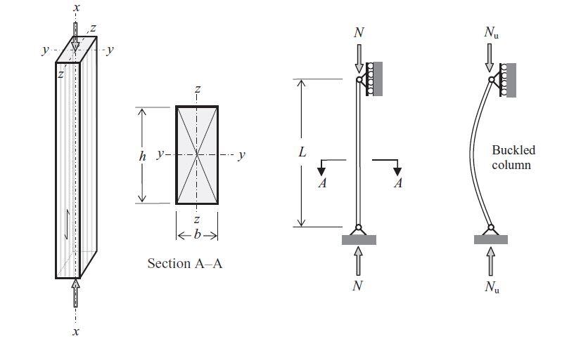
The slenderness ratio is defined as the effective length of the member, Le, divided by its radius of gyration, i,;
λ = Le/i
where the radius of gyration about an axis i = √I/A, I is the second moment of area about the axis, and A is the cross-sectional area of the member. For any member, there will be a slenderness ratio, λy, about the y–y axis and, λz, about the z–z axis and when using a rectangular section, as shown in section A–A in Figure 3.
Design Example
Verify the capacity of 200 mm x 100 mm timber section of strength class C18 to satisfy ultimate limit state requirements under the following conditions:
Service Condition: Class 2
Characteristic permanent action Gk = 10 kN
Variable medium-term action Qk = 25 kN
Height of column = 3.0m
Support condition: Effectively held in position but not in direction in both axes.
Solution
Geometric properties
Depth of member h = 200 mm
Width of member b = 100 mm
Area of member A = bh = 200 x 100 = 20000 mm2
Second moment of area about the y-y axis Iy = bh3/12 = (100 x 2003)/12 = 6.667 x 107 mm4
Radius of gyration about the y-y axis iy = √(Iy/A) = √(6.667 x 10⁷/20000 ) = 57.74 mm
Second moment of area about the z-z axis Iz = hb3/12 = (200 x 1003)/12 = 1.667 x 107 mm4
Radius of gyration about the z-z axis iz = √(Iz/A) = √(1.667 x 10⁷/20000 ) = 28.86 mm
Effective length about the y-y axis LE,y = Effective length about the z-z axis LE,z = 1.0 L = 3000 mm
Therefore slenderness ratio about the y-y axis;
λy = LE,y/iy =3000/57.74 = 51.957
The slenderness ratio about the z-z axis;
λz = LE,z/iz =3000/28.86 = 103.95
Timber Properties (Table 1 BS EN 338:2003(E))
For strength class C18;
Characteristic compression strength parallel to the grain fc.0.k = 18 N/mm2
Fifth percentile modulus of the elasticity parallel to the grain E0.05 = 6.0 kN/mm2
Partial safety factors
UKNA to BS EN 1990:2002, Table NA.A1.2(B)) for the ULS
Permanent actions, γG = 1.35
Variable actions, γQ = 1.5
Material factor for solid timber, γM = 1.3 (UKNA to EC5, Table NA.3)
Design Action
Design Action at ultimate limit state NEd = 1.35Gk + 1.5Qk
NEd = 1.35(10) + 1.5(25) = 51 kN = 51000 N
Modification factors
Factor for medium duration loading and service class 2, kmod.med = 0.8 (EC5, Table 3.1)
System strength factor, (not relevant) ksys = 1.0
Therefore, the design compression stress αc,0,d = NEd/A = 51000/20000 = 2.55 N/mm2
The design compression strength fc,0,d = (kmod.med ksys fc.0.k)/ γM
fc,0,d = (0.8 x 1.0 x 18)/1.3 = 11.08 N/mm2
Buckling Resistance (clause 6.3.2 EC5)
Relative slenderness about the y-y axis
λrel,y = (λy /π) x √(fc.0.k/E0.05) = (51.957/π) x √(18/6000) = 0.9058 (equation 6.21 EC5)
Relative slenderness about the z-z axis
λrel,z = (λz /π) x sqrt(fc.0.k/E0.05) = (103.95/π) x √(18/6000) = 1.81 (equation 6.21 EC5)
As both relative slenderness ratios are greater than 0.3, the conditions in clause 6.3.2(3):
Maximum relative slenderness ratio of the column = λrel,z = 1.81
Factor βc for solid timber βc = 0.2 (EC5, equation (6.29))
The factor kz (equation 6.28 EC5)
kz = 0.5[1 + 0.2(1.81 – 0.3) + 1.812] = 2.289
Instability factor (equation 6.26 EC5)
kzc = 1/[2.289 + √(2.2892 – 1.812)] = 0.27
Design buckling strength kzc .fc,0,d = 0.27 x 11.08 = 2.9916 N/mm2
Therefore, design stress/design buckling strength ratio = 2.55/2.9916 = 0.852 < 1.0 Ok
Therefore, the section is satisfactory.





• Hello! Someone in my Myspace group shared this site with us so I came to take a look. I’m definitely loving the information. I’m book-marking and will be tweeting this to my followers! Exceptional blog and superb style and design.
bim services
bim servicesin USA
bim servicesin Uk
Nice work.
Nice work.
Keep up !