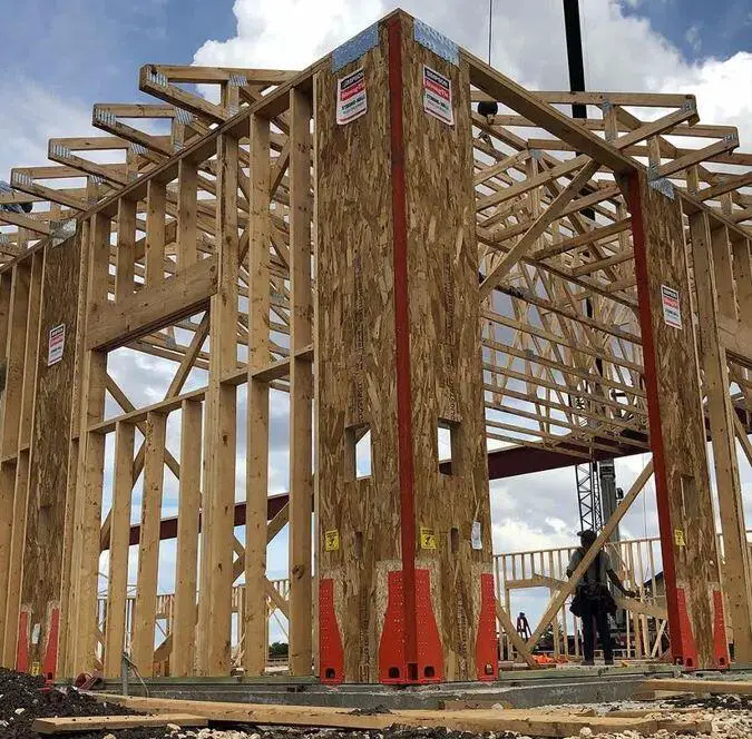
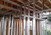
Timber shear (stud) walls are an essential part of the structural system of timber structures/buildings. They are typically made up of a frame of vertical timber studs sheathed with plywood or other structural sheet material.
In the design of timber frame structures, one of the significant functions of walls is to provide load-bearing support and stability for vertical actions from the floor (decking) and roof (rafters or trusses), and also to provide strength and stability against the effects of lateral actions. These walls also accommodate various architectural features such as doors, windows, and built-in shelving.
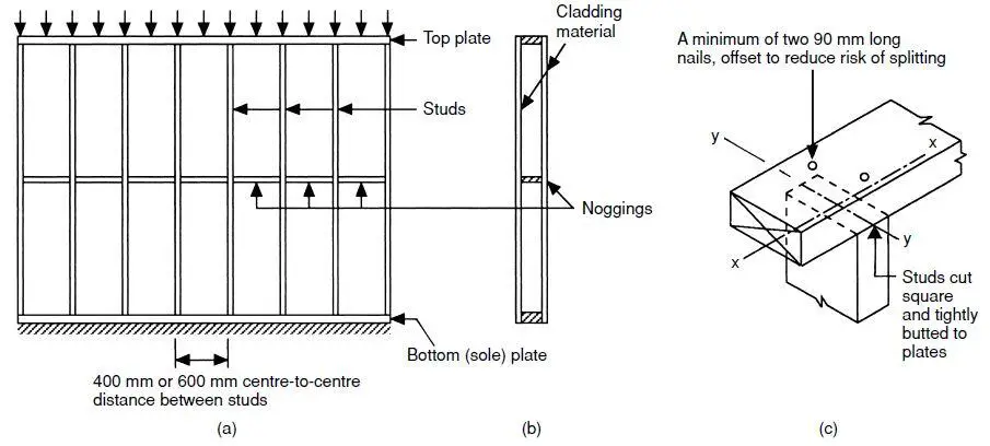
A timber stud wall is a type of wall that is made up of a frame of vertical timber studs (structural wooden posts), which are spaced evenly apart and held in place by horizontal plates at the top (header plates) and bottom (sole plates) of the wall. The studs are typically made of 75mm x 50mm or 100mm x 50mm sawn timber, and the spacing between them is typically between 450mm to 600mm.
Timber shear walls provide lateral resistance to wind and seismic forces, helping to keep the structure from undergoing failure due to lateral actions. The plywood sheathing helps to transfer the lateral forces to the studs, which then resists the forces by bending and shearing.
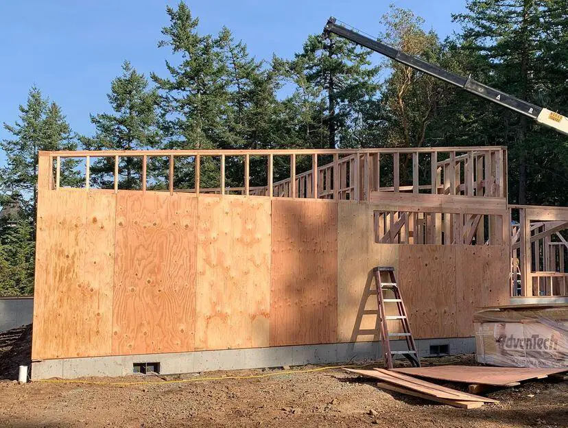
Design of Stud Walls
As stated above, the vertical components in a timber shear wall system are commonly known as studs, while the walls are typically referred to as stud walls. These studs are aligned with their stronger axis (y-y) parallel to the wall’s surface and are securely positioned by the header and sole plates. Battens or noggins are utilized for in-plane stability, preventing lateral movement through diagonal or equivalent bracing members. These battens serve a dual purpose, both during construction and in persistent design scenarios.
In situations where the wall sheathing cannot provide sufficient lateral resistance, the use of diagonal or equivalent bracing (noggins) compensates for this. In such cases, the effective length of the stud around the z-z axis is determined by the longest span of stud between the plate and batten support.
When the sheathing material can provide adequate lateral restraint, concerns about stud buckling around the z-z axis can be disregarded. The sheathing material provided it is fixed to the studs and plates as per the manufacturer’s guidelines or design requirements, offers satisfactory lateral resistance. However, if sheathing is affixed to only one side of the wall, complete lateral restraint for the studs is not achieved, necessitating the use of a reduced effective length.
Stud walls are unlikely to exhibit any form of fixity at their ends. In the case of out-of-plane buckling around the y-y axis, the studs are deemed to be securely held in place and torsionally restrained by the fastenings to the header and sole plates. Nonetheless, these studs are allowed to rotate laterally at these points. Consequently, the effective length of the stud in relation to this axis is assumed to be equivalent to the height of the stud wall.
Timber stud analysis and design example (EN1995-1-1:2004)
In accordance with EN1995-1-1:2004 + A2:2014 incorporating corrigendum June 2006 and the UK national annex.
Stud details
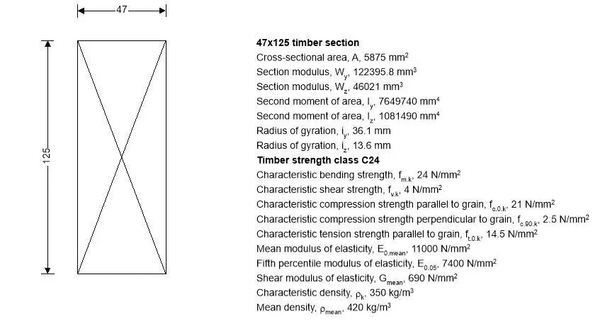
Description; 47 x 125 C24 timber studs
Restraint in plane of panel; Sheathing
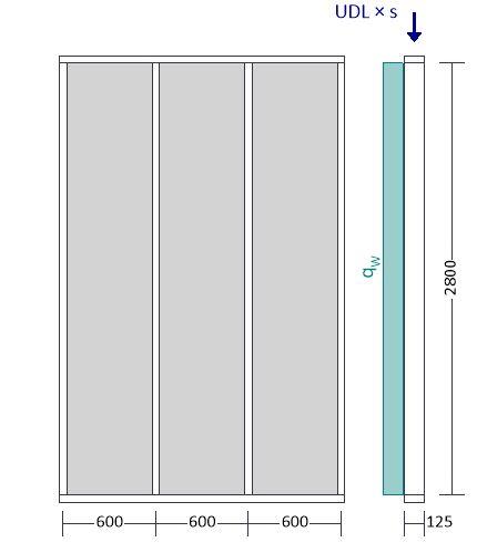
Stud spacing; sStud = 600 mm
Stud height; lStud = 2800 mm
Panel height; lPanel = lStud + 2b = 2894 mm
Forces input on Stud
Lateral wind load; HW_Z0_Stud = 1.50 kN/m2
Permanent distributed load on top rail; LG_Stud = 5.60 kN/m
Imposed distributed load on top rail; LQ_Stud = 8.40 kN/m
Stud loading details
Lateral wind load;
pW,h0 = HW_Z0_Stud × sStud = 0.90 kN/m
Total vertical permanent point load (2800 mm);
PG_1 = LG_Stud × sStud = 3.36 kN
Total vertical imposed point load (2800 mm);
PQ_1 = LQ_Stud × sStud = 5.04 kN
Member Loads
The summary of the member loads is shown in the Table below.
| Member | Load case | Load Type | Orientation | Description |
| Member | Permanent | Point load | GlobalZ | 3.36 kN at 2.8 m |
| Member | Imposed | Point load | GlobalZ | 5.04 kN at 2.8 m |
| Member | Wind | UDL | GlobalX | 0.9 kN/m at 0 m to 2.8 m |
Loading Combinations
The load combinations used in the analysis of the structure are shown in the Table below.
| Load combination | Permanent | Imposed | Snow | Wind |
| 1.35G + 1.5Q (Strength) | 1.35 | 1.50 | 0.00 | 0.00 |
| 1.35G + 1.5Q + ψS1.5S + ψW1.50W (Strength) | 1.35 | 1.50 | 0.75 | 0.75 |
| 1.0G + 1.5W (Strength) | 1.00 | 0.00 | 0.00 | 1.50 |
| 1.00G + 1.0Q (Service) | 1.00 | 1.00 | 0.00 | 0.00 |
| 1.00G + 1.0Q + ψS1.0S +ψW1.0W (Service) | 1.00 | 1.00 | 0.50 | 0.50 |
| 1.0G + 1.0W (Service) | 1.00 | 0.00 | 0.00 | 1.00 |
Support reactions
The support reactions from the load combinations are shown below.
| Load case/combination | Fx (kN) | Fz (kN) |
| 1.35G + 1.50Q (Strength) | 0 | 12.2 |
| 1.35G + 1.50Q + ψS1.50S + ψW1.50W (Strength) | -1.9 | 12.2 |
| 1.0G + 1.50W (Strength) | -3.8 | 3.4 |
| 1.00G + 1.00Q (Service) | 0 | 8.5 |
| 1.00G + 1.00Q + ψS1.00S + ψW1.00W (Service) | -1.3 | 8.5 |
| 1.0G + 1.00W (Service) | -2.5 | 3.4 |
Member Envelope (Strength)
| Position (m) | Shear force (kN) | Moment (kNm) | ||
| 0 | 1.9 (max abs) | 0 | 0 | |
| 1.4 | 0 | 1.3 (max) | 0 | |
| 2.8 | 0 | -1.9 | 0 | |
Partial factor for material properties – Table 2.3;
γM = 1.300
Member details
Load duration – cl.2.3.1.2; Short-term
Service class – cl.2.3.1.3; 2
Timber section details
Number of timber sections in member; N = 1
Breadth of sections; b = 47 mm
Depth of sections; h = 125 mm
Timber strength class – EN 338:2016 Table 1; C24
Bearing length; Lb = 100 mm
Modification factors
Duration of load and moisture content – Table 3.1; kmod = 0.9
Deformation factor – Table 3.2; kdef = 0.8
Depth factor for bending – Major axis – exp.3.1; kh,m,y = min((150 mm / h)0.2, 1.3) = 1.037
Bending stress re-distribution factor – cl.6.1.6(2); km = 0.7
Crack factor for shear resistance – cl.6.1.7(2); kcr = 0.67
Load configuration factor – cl.6.1.5(4); kc,90 = 1
System strength factor – cl.6.6; ksys = 1.1
Check compression parallel to the grain – cl.6.1.4
Design axial compression; Pd = 3.428 kN
Design compressive stress; σc,0,d = Pd / A = 0.583 N/mm2
Design compressive strength; fc,0,d = kmod × ksys × fc.0.k / γM = 15.992 N/mm2
σc,0,d / fc,0,d = 0.036
PASS – Design parallel compression strength exceeds design parallel compression stress
Compression perpendicular to the grain – cl.6.1.5
Design perpendicular compression – major axis; Fc,y,90,d = 1.89 kN
Effective contact length; Lb,ef = Lb = 100 mm
Design perpendicular compressive stress – exp.6.4;
σc,y,90,d = Fc,y,90,d / (b × Lb,ef) = 0.402 N/mm2
Design perpendicular compressive strength;
fc,y,90,d = kmod × ksys × fc.90.k / γM = 1.904 N/mm2
σc,y,90,d / (kc,90 × fc,y,90,d) = 0.211
PASS – Design perpendicular compression strength exceeds design perpendicular compression stress
Check shear force – Section 6.1.7
Design shear force; Fy,d = 1.89 kN
Design shear stress – exp.6.60; τy,d = 1.5Fy,d / (kcr bh) = 0.720 N/mm2
Design shear strength;
fv,y,d = kmod × ksys × fv.k / γM = 3.046 N/mm2
τy,d / fv,y,d = 0.236
PASS – Design shear strength exceeds design shear stress
Compression or combined compression and bending – cl.6.3.2
Effective length for y-axis bending;
Le,y = 0.9 × 2800 mm = 2520 mm
Slenderness ratio;
λy = Le,y / iy = 69.836
Relative slenderness ratio – exp. 6.21;
λrel,y = λy / π × √(fc.0.k / E0.05) = 1.184
Effective length for z-axis bending; Le,z = 0 mm
Slenderness ratio;
λz = Le,z / iz = 0
Relative slenderness ratio – exp. 6.22;
λrel,z = λz / π × √(fc.0.k / E0.05) = 0
λrel,y > 0.3 column stability check is required
Straightness factor; βc = 0.2
Instability factors – exp.6.25, 6.26, 6.27 & 6.28;
ky = 0.5 × (1 + βc(λrel,y – 0.3) + λrel,y2) = 1.290
kz = 0.5 × (1 + βc(λrel,z – 0.3) + λrel,z2) = 0.470
kc,y = 1 / (ky + √(ky2 – lrel,y2)) = 0.556
kc,z = 1 / (kz + √(kz2 – lrel,z2)) = 1.064
Column stability checks – exp.6.23 & 6.24;
σc,0,d / (kc,y fc,0,d) = 0.066
σc,0,d / (kc,zfc,0,d) = 0.034
PASS – Column stability is acceptable
Check design 1400 mm along span (Mid-span)
Check bending moment – Section 6.1.6
Design bending moment; My,d = 1.323 kNm
Design bending stress; σm,y,d = My,d / Wy = 10.809 N/mm2
Design bending strength;
fm,y,d = kh,m,y × kmod × ksys × fm.k / γM = 18.956 N/mm2
σm,y,d / fm,y,d = 0.57
PASS – Design bending strength exceeds design bending stress
Combined bending and axial compression – Section 6.2.4
Combined loading checks – exp.6.19 & 6.20;
(σc,0,d / fc,0,d)2 + σm,y,d / fm,y,d = 0.572
(σc,0,d / fc,0,d)2 + km × σm,y,d / fm,y,d = 0.400
PASS – Combined bending and axial compression utilisation is acceptable
Compression or combined compression and bending – cl.6.3.2
Effective length for y-axis bending;
Le,y = 0.9 × 2800 mm = 2520 mm
Slenderness ratio;
λy = Le,y / iy = 69.836
Relative slenderness ratio – exp. 6.21;
λrel,y = λy / π × √(fc.0.k / E0.05) = 1.184
Effective length for z-axis bending;
Le,z = 0 mm
Slenderness ratio;
lz = Le,z / iz = 0
Relative slenderness ratio – exp. 6.22;
λrel,z = λz / π × √(fc.0.k / E0.05)= 0
lrel,y > 0.3 column stability check is required
Straightness factor; βc = 0.2
Instability factors – exp.6.25, 6.26, 6.27 & 6.28;
ky = 0.5(1 + βc(λrel,y – 0.3) + λrel,y2) = 1.290
kz = 0.5(1 + βc(λrel,z – 0.3) + λrel,z2) = 0.470
kc,y = 1 / (ky + √(ky2 – λrel,y2)) = 0.556
kc,z = 1 / (kz + √(kz2 – λrel,z2)) = 1.064
Column stability checks – exp.6.23 & 6.24;
σc,0,d / (kc,yfc,0,d) + σm,y,d / fm,y,d = 0.636
σc,0,d / (kc,zfc,0,d) + σm × sm,y,d / fm,y,d = 0.433
PASS – Column stability is acceptable
Check beams subjected to either bending or combined bending and compression – cl.6.3.3
Lateral buckling factor – exp.6.34; kcrit = 1.000
Beam stability check – exp.6.35;
(σm,y,d / (kcritfm,y,d))2 + σc,0,d / (kc,zfc,0,d) = 0.359
PASS – Beam stability is acceptable
Conclusion
Timber shear wall design in accordance with the Eurocodes involves the structural analysis and design of timber-framed walls (stud walls) to resist gravity (such as floor and roof loads) and lateral loads (such as wind or seismic forces). Timber shear walls are typically made up of a frame of vertical timber studs, which are sheathed with plywood or other structural sheet material. The plywood sheathing helps to transfer the lateral forces to the studs, which then resist the forces by bending and shearing.
The structural design of timber shear walls involves the determination of the appropriate timber stud section, grade, spacing, and sheating material that will effecively and economically resist the anticipated design loading. The design must therefore take into account a number of factors, including the wind and seismic loads that the wall will be subjected to, the height and length of the wall, the type and thickness of the plywood sheathing, the size and spacing of the timber studs, and the type of connections between the studs and the plywood sheathing.
In addition to the design standards, the structural design of timber shear walls must also consider the following factors: the moisture content of the timber, the fire resistance requirements of the wall, the insulation requirements of the wall, and the cost of the wall. By carefully considering all of these factors, the structural engineer can design timber shear walls that are strong, stable, and cost-effective.

