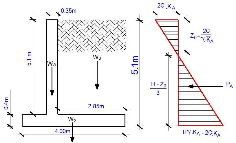
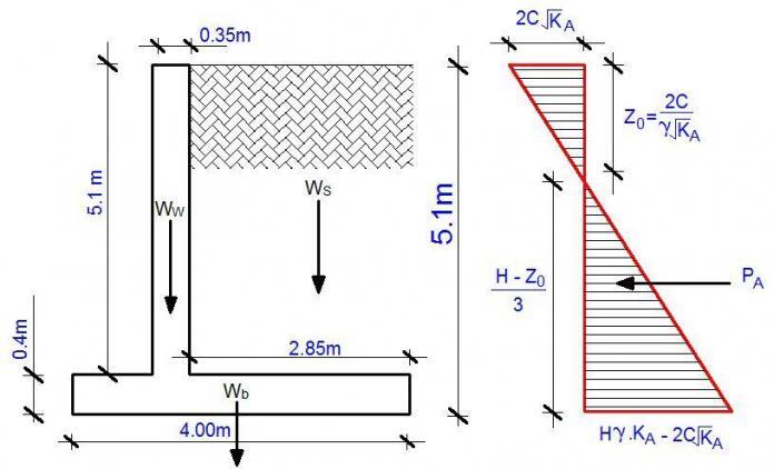
Cohesive soil profiles due to their nature are partially self supporting up to an extent called the critical depth (the critical depth is given by 2Zo, kindly see figure above). As a result, such soils would not exert much pressure on a retaining wall as a granular material would (especially considering active earth pressure). Tropical laterites (especially those found in Nigeria) usually possess angle of internal friction and some cohesion. Their usage for construction purposes is also widespread.
The walls retaining such soils are subjected to active and passive pressure. In this example, we are going to consider active pressure only (all passive pressure neglected), but note that passive pressure could be more critical and hence govern the design (I recommend you read standard geotechnical engineering textbooks for more knowledge on this subject).
Worked Example
The cantilever retaining wall shown below is backfilled with tropical lateritic earthfill, having a unit weight, ρ, of 18 kN/m3, a cohesion C of 8 kN/m3 and an internal angle of friction, φ, of 26°. The allowable bearing pressure of the soil is 150 kNm/2, the coefficient of friction is 0.5, and the unit weight of reinforced concrete is 24 kN/m3. Water level is at a great depth and adequate drainage is provided at the back of the wall.
We are to;
1. Determine the factors of safety against sliding and overturning for the active pressure.
2. Calculate ground bearing pressures.
3. Design the wall and base reinforcement assuming fcu = 30 N/mm2, fy = 460 N/mm2 and the cover to reinforcement in the wall and base are, respectively, 40 mm and 50 mm.
Geotechnical Design
Wall Pressure Calculations

Coefficient of active pressure KA
Using Rankine’s theory
KA = (1 – sinφ) / (1 + sinφ);
KA = (1 – sin 26°) / (1 + sin 26°) = 0.39046;
Pressure at the top of wall = 2C√KA = 2 × 8 × √0.39046 = 9.998 kN/m2
Z0 = 2 C/γ√KA = (2 × 8)/(18 × √0.39046) = 1.423m
Pressure at the bottom of retaining wall = H.γ.KA – 2C√KA = (5.5 × 18 × 0.39046) – (2 × 8 × √0.39046) = 32.408 kN/m2
Resistance to Sliding
Consider the forces acting on a 1 m length of wall. Horizontal force on wall due to backfill, PA, is;
PA = 0.5 × 32.408 × 4.077 = 66.063 kN/m
Weight of wall (Ww) = 0.35 × 5.1 × 24 = 42.84 kN/m
Weight of base (Wb) = 0.4 × 4 × 24 = 38.4 kN/m
Weight of soil (Ws) = 2.85 × 5.1 × 18 = 261.63 kN/m
Total vertical force (Wt) = 324.87 kN/m
Friction force, FF, is
FF = μWt = 0.5 × 324.87 = 171.435 kN/m
Neglecting all passive pressure force (FP) = 0.
Hence factor of safety against sliding is;
F.O.S = FF/PA = 171.435/66.063 = 2.595
The factor of safety 2.595 > 1.5. Therefore the wall is very safe from sliding.
Resistance to Overturning
Taking moments about the toe, sum of overturning moments (MO) is;
MO = (66.063 kN/m) × (4.077/3) = 89.779 kN.m
Sum of Restoring Moment MR;
MR = (Ww × 0.975m) + (Wb × 2m) + (Ws × 2.575m)
MR = (42.84 × 0.975m) + (38.4 × 2m) + (261.63 × 2.575m) = 792.266 kNm
F.O.S = MR / MO = 792.266/89.779 = 8.824
The factor of safety 8.824 > 2.0. Therefore the wall is very safe from overturning.
Bearing Capacity Check
Bending moment about the centre line of the base;
M = [66.064 × (4.077/3)] + (Ww × 1.025m) – (Ws × 1m)
M = [66.064 × (4.077/3)] + (42.84 × 1.025m) – (261.63 × 0.575m) = -16.745 kNm
Total vertical load = 324.87 kN
The eccentricity (e) = M/N = (16.745/324.87) = 0.0515m
Let us check D/6 = 4/6 = 0.666
Since e < D/6, there is no tension in the base
The maximum pressure in the base;
qmax = P/B (1 + 6e/B) = 324.87/4 [1 + (6 × 0.0515)/(4)] = 87.491 KN/m2
87.491 KN/m2 < 175 KN/m2
Therefore, the bearing capacity check is satisfied.
Structural Design
Design of the Wall
Conservatively taking the moment at the base of the wall due to the active force;
M = [66.064 × (4.077/3)] = 89.781 kN.m
At ultimate limit state M = 1.4 × 89.781 = 125.693 kN.m
Thickness of wall = 350mm
Effective depth = 350 – 40 – (8) = 302mm (assuming Y16mm bars will be employed for the construction)
k = M/(Fcubd2) = (125.693 × 10⁶) / (30 × 1000 × 3022) = 0.0459
k < 0.156, no compression steel needed
la = 0.5 + (0.25 – k/0.9)0.5 = 0.5 + (0.25 – 0.0459/0.9)0.5 = 0.946
ASreq = M/(0.95Fy.la.d ) = (125.693 × 10⁶) / (0.95 × 460 × 0.946 × 302) = 1006 mm2/m
ASmin = (0.13bh)/100 = (0.13 × 1000 × 350) / 100 = 455 mm2
Provide Y16 @ 150mm c/c (Asprov = 1340 mm2/m)
Check for shear
Design shear force on wall at ultimate limit state V = (1.4 × 66.064) = 92.4896 kN/m
Shear stress v = V/bd = (92.4896 × 1000) / (1000 × 302) = 0.3062 N/mm2
Vc = 0.632 (100As/bd)1/3 (400/d)1/4
Vc = 0.632 × [(100 × 1340)/(1000 × 302)]1/3 × (400/302)1/4
Vc = 0.632 × 0.7627 × 1.0727 = 0.517 N/mm2
For Fcu = 30N/mm2, Vc = 0.517 × (30/25)1/3 = 0.5494 N/mm2
Since v < Vc, no shear reinforcement required.
Design of the Base
The pressure distribution diagram on the base at serviceability limit state is as shown below;
qmax = P/B (1 + 6e/B) = 324.87/4 [1 + (6 × 0.0515)/(4)] = 87.491 kN/m2
qmin = P/B (1 – 6e/B) = 324.87/4 [1 – (6 × 0.0515)/(4)] = 74.927 kN/m2
At ultimate limit state;
qmax = 1.4 × 87.491 = 122.487 KN/m2
qmin = 1.4 × 74.927 = 104.898 KN/m2
qC = 104.898 + [2.85 (122.487 – 104.898)]/4 = 117.430 kN/m2
qB = 104.898 + [3.2 (122.487 – 104.898)]/4 = 118.968 kN/m2
On investigating the maximum design moment about point C;
Back fill = 1.4 (18 × 5.1 × 2.85 × 2.85/2) = -521.952 kNm
Heel Slab = 1.4 (24 × 0.4 × 2.85 × 2.85/2) = -54.583 kNm
Earth Pressure = (104.898 × 2.85 × 2.85/2) + [(117.430 – 104.898) × 0.5 × 2.85 × 2.85/3] = 426.017 + 16.965 = 442.982 KNm
Net moment = -521.952 – 54.583 + 442.982 = -133.553 kNm
On investigating the maximum design moment about point B;
Back fill = (conservatively neglected)
Heel Slab = 1.4 (24 × 0.4 × 0.8 × 0.8/2) = – 4.3008 kNm
Earth Pressure = (118.968 × 0.8 × 0.8/2) + [(122.487 – 118.968) × 0.5 × 0.8 × (2 × 0.8/3)] = 37.9776 + 0.751 = 38.727 kNm
Net moment = -4.3008 + 38.727 = 34.426 kNm
Design of the toe
MB = 133.553 kN.m
Thickness of base = 400 mm
Effective depth = 400 – 50 – (8) = 342 mm (assuming Y16mm bars will be employed for the construction)
k = M/(Fcubd2) = (133.553 × 10⁶) / (30 × 1000 × 3422) = 0.0385
k < 0.156, no compression steel needed
la = 0.5 + (0.25 – k/0.9)0.5 = 0.5 + (0.25 – 0.0385/0.9)0.5 = 0.95
ASreq = M/(0.95Fy.la.d ) = (133.553 × 10⁶) / (0.95 × 460 × 0.95 × 342) = 941 mm2/m
ASmin = (0.13bh)/100 = (0.13 × 1000 × 400) / 100 = 520 mm2
Provide Y16 @ 175 mm c/c Top (Asprov = 1148 mm2/m)
Design of the heel
MC = 34.426 KNm
Thickness of base = 400 mm
Effective depth = 400 – 50 – (6) = 344 mm (assuming Y12mm bars will be employed for the construction)
k = M/(Fcubd2) = (34.426 × 10⁶) / (30 × 1000 × 3442) = 0.00981
k < 0.156, no compression steel needed
la = 0.5 + (0.25 – k/0.9)0.5 = 0.5 + (0.25 – 0.00981/0.9)0.5 = 0.95
ASreq = M/(0.95Fy.la.d ) = (34.426 × 10⁶) / (0.95 × 460 × 0.95 × 344) = 242 mm2/m
ASmin = (0.13bh)/100 = (0.13 × 1000 × 400) / 100 = 520 mm2
Provide Y12 @ 175mm c/c (Asprov = 646 mm2/m)
Check for shear at the base
The maximum shear force at ‘d’ from the face of the wall is investigated at the either side;
Maximum shear force at point B
Earth fill = 1.4 × 18 × 5.1 × 2.85 = -366.282 kN/m
Wall base = 1.4 × 24 × 0.4 × 2.85 = -38.304 kN/m
Base Earth Pressure = 0.5 (104.898 + 117.430) × 2.85 = 316.817 kN/m
Net shear force = -366.282 – 38.304 + 316.817 = -87.769 kN/m
A little investigation will show that this is the maximum shear force at any section on the base.
Taking the maximum shear stress at the base v = (87.769 × 1000) / (1000 × 342) = 0.2566 N/mm2
Vc = 0.632 (100As/bd)1/3 (400/d)1/4
Vc = 0.632 × [(100 × 1148) / (1000 × 342)]1/3 × (400/342)1/4
Vc = 0.632 × 0.694 × 1.0399 = 0.456 N/mm2
For Fcu = 30N/mm2, Vc = 0.456 × (30/25)1/3 = 0.484 N/mm2
Since v < Vc, no shear reinforcement required.
DETAILING
I will need my readers to do the detailing sketches. I will accept both manual (hand) and CAD details. But your manual sketches must be very neat and well scaled. You should show the plans and at least one section. If your detailing is good enough, I will publish it on this post with your Facebook, LinkedIn, or G+ URL attached.
So, I will keep updating the post with as many good pictures as I receive. Good knowledge for all to flourish @ Structville
Send your sketches and URL profile to info@structville.com
Thank you for visiting Structville…
Our Facebook page is at www.facebook.com/structville


A very good and nice article . I appreciate it. Keep it up.
great work!! keep it up
Thank you..
Great work engineer
Muito didático. Obrigada.
Pressure a the bottom should be 28.66
and also Pa =58.43
Hi,
Very good job please can I have it by email.
Thanks for the sharing
Best regards
goods
Cantilever retaining walls are effective for supporting significant loads, thanks. What are the primary benefits of using a cantilever design over other types?