The analysis of seepage behaviour (flow of water) within earth dams is an important aspect of the geotechnical design evaluation of such earth structures. Earth dams rely on their structural integrity to safely impound water. However, the flow of water through the pores of the earthen structure must be technically controlled.
An important aspect of the design involves ensuring that the pore pressure at the downstream toe of the dam remains sufficiently low to prevent instability and the exit gradient falls short of the critical value that could induce piping. Understanding and analyzing this flow, often referred to as seepage, is important for dam safety and optimal design.
The primary objective of seepage analysis lies in determining the location of the free water surface within the dam, commonly referred to as the phreatic surface (see Figure 1). By definition, the pressure head along the phreatic surface is zero.

Mechanisms of Water Flow
The primary mechanism governing water flow through earth dams is the hydraulic gradient. This gradient represents the difference in water pressure head between two points and dictates the direction and velocity of water movement. In the context of earth dams, the hydraulic gradient drives water from the upstream reservoir (high pressure) towards the downstream side (low pressure) through the pores and voids within the dam’s soil matrix.
The rate of water flow is directly proportional to the hydraulic gradient and the coefficient of permeability (k) of the dam material. Permeability is a measure of a material’s ability to transmit fluids and varies depending on the soil composition, grain size distribution, and void ratio. Finer-grained soils with smaller voids typically exhibit lower permeability, hindering water flow.
There are two main flow regimes within an earth dam:
- Darcy’s Law flow: This regime governs flow at low hydraulic gradients. It is described by Darcy’s Law, which states that the seepage velocity (v) is equal to the product of the hydraulic conductivity (k) of the soil, the hydraulic gradient (dz/dx), and the effective porosity (n) of the material.
- Dupuit-Forchheimer flow: At higher hydraulic gradients, nonlinear flow behaviour can occur due to turbulent effects. This regime is often approximated by Dupuit-Forchheimer’s equation, which incorporates additional terms to account for these nonlinearities.
Determination of Phreatic Surface
Casagrande (1937) proposed a method to approximate the phreatic surface (free water surface) within earth dams using a parabola with adjustments at entry and exit points (Figure 1). The centre of this parabola (focus, point F) is located at the downstream toe of the dam.
This initial, uncorrected parabolic representation is referred to as the “basic parabola.” Recalling the geometric definition, a parabola has the property where every point on its curve is equidistant to the focus (F) and a specific line called the directrix. To construct this basic parabola, three key elements are needed:
- Point A (location not explicitly defined here)
- Focus (F) at the downstream toe
- f (half the distance from the focus to the directrix)
Casagrande further recommended that point C, another point on the parabola, be positioned at a distance of 0.3 times the horizontal projection (AB) of the upstream slope at the water surface level. Based on the fundamental property of a parabola, the passage then leads into the subsequent calculations. From the basic property of a parabola, we get;
2f = √(b2 + H2) – b
The equation to construct the basic parabola is;
√(x2 + z2) = x + 2f
Solving for z, we obtain;
z2 = 4f(f + x) or
z = 2√f(f + x) ——– (1)
Since H and b are known from the geometry of the dam, the basic parabola can be constructed. We now have to make some corrections at the upstream entry point and the downstream exit point.
The abrupt change in geometry at the upstream end is addressed by introducing a transition curve (designated as BE) that seamlessly integrates with the underlying parabolic profile. The downstream end correction is contingent upon the angle designated as “b” and the specific discharge face configuration.
Casagrande (1937) established a methodology for determining the length (denoted as “a”) of the discharge face for a homogeneous earth dam lacking a drainage blanket at the discharge point, provided the angle “b” is less than 30 degrees. His approach is based on the validity of Dupuit’s assumption, which posits that the hydraulic gradient aligns precisely with the slope (dz/dx) of the phreatic surface.
To facilitate the analysis, we consider two vertical sections: section KM with a height of “z” and section GN with a height of “a sin b.” Thus, the flow rate traversing section KM…
qKM = Aki = (z × 1)k(dz/dx) ——– (2)
and across GN is;
qGN = Aki = (a sin β × 1)k(dz/dx) = (a sin β × 1)k tan β ——– (3)
From the continuity condition at sections KM and GN, qKM = qGN, we obtain:
z(dz/dx) = a sin β tan β ——– (4)
Integrating the equation within the limits x1 = a cos β and x2 = b, z1 = a sin β and z2 = H, we obtain;
a = 1/cosβ × [(b – √(b2 – H2cot2β)] ——– (5)
The flow through the dam is obtained by substituting Equation (5) into Equation (3), giving;
q = k sin β tan β × 1/cosβ × [(b – √(b2 – H2cot2β)]
= k tan2 β (b – √(b2 – H2cot2β)
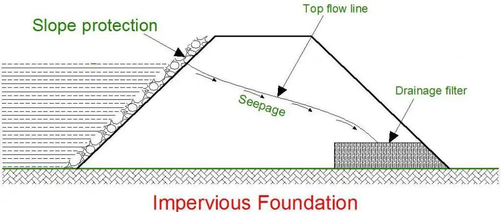
To mitigate the issue of high exit hydraulic gradients and potential piping problems, drainage filters are installed at the downstream toe of dams. As illustrated in Figure 3, a horizontal drainage blanket is positioned at the toe of the earth dam. The coarseness of the granular materials within the drainage blanket, along with the presence or absence of a filter fabric, dictates the control of seepage.

In dams incorporating drainage blankets, the phreatic surface is compelled to intersect the blanket, rather than the downstream dam face. Consequently, there is no requirement for modifications to the fundamental parabolic profile at the downstream end of the dam.
The flow through the dam is:
q =Aki = Ak(dz/dx)
Where dz/dx is the slope of the basic parabola and the area A = FJ = 1.0. From the geometry of the basic parabola, FJ = 2f, and the slope of the basic parabola at J is given by:
dz/dx = 2f/z = 2f/2f = 1.0
Therefore the flow through an earth dam with a horizontal drainage blanket is:
q = 2f × k × 1 = 2fk
Steps in drawing a phreatic surface through an Earth Dam
According to Budhu (2010), the following steps can be followed in determining the phreatic surface through earth dams:
- Draw the structure to scale.
- Locate a point A at the intersection of a vertical line from the bottom of the upstream face and the water surface, and a point B where the water line intersects the upstream face.
- Locate point C, such that BC = 0.3AB.
- Project a vertical line from C to intersect the base of the dam at D.
- Locate the focus of the basic parabola. The focus is located conveniently at the toe of the dam.
- Calculate the focal distance, f = (√(b2 – H2) – b)/2 where b is the distance FD and H is the height of water on the upstream face.
- Construct the basic parabola from z = 2√f(f + x).
- Sketch in a transition section BE.
- Calculate the length of the discharge face, a, using 1/cosβ × [(b – √(b2 – H2cot2β)] (where β ≤ 30 degrees)
- Measure the distance ‘a’ from the toe of the dam along the downstream face to point G.
- Sketch in a transition section, GK.
- Calculate the flow using q = ak sin β tan β, where k is the hydraulic conductivity. If the downstream slope has a horizontal drainage blanket, the flow is calculated using q = 2fk.
This procedure provides a framework for analyzing seepage flow through earth dams, incorporating both geometric considerations and material properties to estimate potential flow rates.
Mitigation Strategies
To ensure the stability and safety of earth dams, various strategies are employed to manage water flow:
- Drainage blankets: These are coarse-grained materials placed at the downstream toe of the dam. They act as a collector for seepage water, lowering the exit hydraulic gradient and reducing the risk of piping. Filter fabrics are often used in conjunction with drainage blankets to prevent soil migration from the dam into the drainage layer.
- Impervious cores: A core of low-permeability material, such as clay, can be placed within the dam’s central section to significantly reduce seepage flow through the dam itself.
- Relief wells: These are vertical wells drilled downstream of the dam to intercept seepage water and lower the phreatic surface (water table) within the dam.
- Seepage berms: These are compacted earth embankments constructed downstream of the dam to lengthen the seepage path and reduce the exit hydraulic gradient.
Sources and Citations
Budhu M. (2011): Soil Mechanics and Foundations (3rd Edition). Wiley and Sons Inc. USA
Casagrande A. (1937): Seepage through dams. J. N. Engl. Water Works Assoc., L1(2), 131–172.

