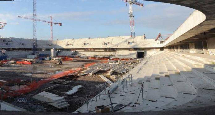
One of the most common concepts for the construction of sports stadiums today involves having precast concrete terrace units (seating decks) spanning between raker beams while at the same time, resting on each other. The successive arrangement of these precast seating units on the raker beams forms the grandstand of the stadium. The raker beams are usually formed in-situ with the columns of the structure and form part of the structural frame of the grandstand. It is also feasible to construct precast raker beams as was done in the Corinthians Arena Sao Paolo, Brazil for the 2014 FIFA world cup.
Precast seating decks are usually made of L-shaped reinforced concrete units of length between 7-8 meters spanning between the raker beams. The seating decks also rest on each other. The role of the third (resting support) is to stop the units from undergoing excessive twisting, and in general, provide extra stability.
Seating units are used to span between raker beams and form the exposed surface to which the seats are bolted onto. The seating units are fabricated in moulds depending on the length of the span, angle of inclination/curve, and support conditions. The precast seating units can be easily installed on-site, and when the joints between units have been sealed, they form an effective barrier against external elements. They can also be easily installed in steel structures.
In a 2011 study at the University of Bath, human perception of vibration due to synchronised crowd loading was studied. Standard precast seating decks of 5.6 m length were used for the study. The precast seating decks used in the study were surpluses from a real premiership stadium project. The initial design length was 7.6 m but was cut to 5.6 m for the purpose of the study. The set up of the test rig is shown below.
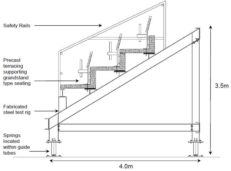
The precast seating deck used in the study was designed according to the requirements of BS 8110-1:1997 with a design live load of 4 kN/m2 for an assembly area with fixed seating. The live load was increased to 5 kN/m2 to allow for dynamic magnification (Browning, 2011). The model was observed to have an empty natural frequency of 6.47 Hz.
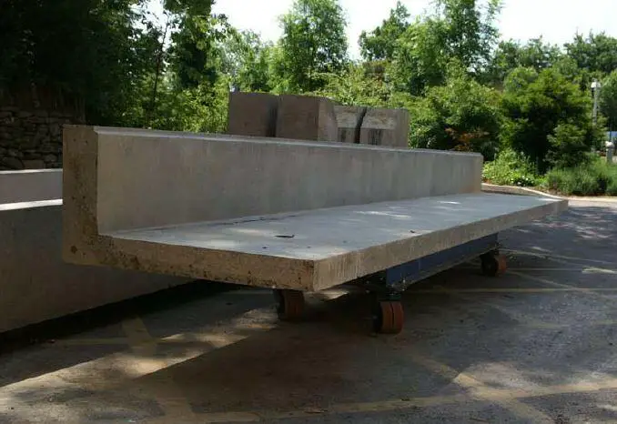
In a 2018 study in Romania, the serviceability of stadium seating decks under dynamic loading was evaluated. In the study, precast seating decks 150 mm thick with a total span of 9.28 m were used. The length of the horizontal flange was 990 mm while the vertical flange was 440 mm. Under the support conditions used in the study, a natural frequency of 6.75 Hz in the unloaded state was observed from the experiment. When numerically evaluated, a natural frequency of 6.76 Hz was observed for the unloaded structure and 4.75 Hz for the loaded structure.
The British design code BS 6399-1 sets the lower limit of the fundamental frequency for vertical vibrations of unloaded seating decks to 8.4 Hz, while the Green Guide (IStructE Dynamic performance for Permanent Grandstands subject to Crowd Action, 2008) set the same limit to 6 Hz but taking into account the weight of people on the structure. The authors concluded from the study that the section satisfied structural safety requirements, but human comfort due to vibration may be a major concern.
Design Example
Let us design a 6m long precast seating deck for a stadium with a section shown below;
fcu = 35 N/mm2; fyv = 460 N/mm2; fy = 460 N/mm2
Concrete cover = 30 mm
Unit weight of concrete = 24 kN/m3
Loading Analysis
Load type = uniformly distributed loading
Dead Load
Self weight of the unit = (24 × 0.15 × 0.25) + (24 × 0.15 × 0.95) = 4.32 kN/m
Make allowance for stair units, seats, and railings = 2 kN/m2
Live Load
For grandstands with fixed seating = 4 kN/m2
Making allowance for dynamic magnification qk = 5 kN/m2
At ultimate limit state;
n = 1.4gk + 1.6qk
n = 1.4(6.32) + 1.6(5) = 16.848 kN/m
Design Moment Mmax @ 3.0m = (ql2)/8 = (16.848 × 62)/8 = 75.816 kN.m
End shears V = ql/2 = (16.848 × 6)/2= 50.544 kN
Design of the section (web) to resist the applied moment
M = 75.816 kN.m
Effective depth d = h – Cc – ∅⁄2 – ∅links
Assuming Y16mm for main bars and Y8mm for links
d = 400 – 30 – 10 – 8 = 352 mm
b = bw = 150mm (since the flange is at the tension zone)
k = M/fcubd2 = (75.816 × 10⁶)/(35 × 150 × 3522) = 0.116
la = 0.5 + √[0.25- 0.116/0.9] = 0.848
ASreq = M/(0.95fy.la.d) = (75.816 × 10⁶)/(0.95 × 460 × 0.848 × 352) = 581.22 mm2
In the web, provide 2Y16mm + 2Y12mm (ASprov = 628 mm2)
Provide 2Y12mm (Asprov = 226 mm2) in the compression zone (as hanger bars)
Spread the As,req also along the width of the tread
Provide Y12 @ 175mm c/c Top and Bottom (Asprov = 646 mm2/m)
Distribution bars
Provide Y10 @ 200mm c/c as closed links
Deflection Check
Basic span/effective depth ratio = 20 (for simply supported beams)
Modification factor for tension reinforcement
Service stress fs = (2fyAsreq)/(3Asprov) = (2 × 460 × 581)/(3 × 628)
fs = 283.715 N/mm2
m.f = 0.55 + (477 – fs) / 120(0.9 + M/bd2)
m.f = 0.55 + (477 – 283.715) / 120(0.9 + 4.079) = 0.873
Modification factor for compression reinforcement
1 + (100A’sprov/bd)/(3 + 100A’sprov/bd) = 1.124
Limiting span/effective depth = 0.873 × 1.124 × 20 = 19.625
Actual span/effective depth = 6000/352 = 17.045
Actual < Limiting, therefore deflection is okay
Design of the section to resist shear
Critical end shear V = 50.544 kN
Shear stress v = V/bd = (50.544 × 10³) / (150 × 352) = 0.957 N/mm2
0.957 N/mm2 < 0.8 √35 < 5 N/mm2
Concrete resistance shear stress
vc = 0.632 × (100As/bd)1/3 × (400/d)1/4
vc =0.632 × [(100 × 628)/(150 × 352)]1/3 × (400/352)1/4
vc = 0.632 × 1.059 × 1.032 = 0.69 N/mm2
For concrete grades greater than 25 N/mm2
vc = vc(fcu/25)1/3 = 0.69 × (35/25)1/3 = 0.772 N/mm2
0.772 N/mm2 < 0.957 N/mm2
0.5 vc < v < (vc + 0.4)
provide minimum links with spacing
sv = (0.95AsvFyv)/0.4bv
(Trying 2 legs of Y8mm bar)
sv = (0.9 5 × 107 × 460)/(0.4 × 150) = 735.62mm
Maximum spacing of links = 0.75d
0.75 × 352 = 264m
Provide Y8 @ 250mm c/c links
Simplified dynamic consideration of the section
BS 6399 part 1: 1996 gave the following limit for the vertical frequency for structures subject to synchronized crowd loads = 8.4 Hz. IStructE Dynamic Performance for permanent Grand Stands (2008) gave the following limits;
3.5 Hz for viewing typical sporting events and classical concerts.
6 Hz for pop concerts and high-profile sporting events.
(3.5 Hƶ is given as the minimum vertical frequency acceptable for an empty grandstand).
The natural frequency for simply supported beams subjected to UDL (when the grandstand is empty, consider dead load only) is given by (considering the first mode of vibration);
fn = π/2[gEdIt/(wL4)]0.5 (See Salyards and Hanagan, 2005)
Where;
Ed = dynamic modulus of elasticity of the concrete.
It = Transformed moment of inertia
L = Span of section
g = acceleration due to gravity (m/s2)
w = Applied load (udl) = gk = 6.32 kN/m
An empirical relationship for concrete’s elastic modulus and dynamic modulus is given below;
Ec = 1.25Ed – 19 (BS 8110-2)
Where both units of Ec and Ed are in kN/mm2
Ec,28 = 20 + 0.2fcu = 20 + 0.2(35) = 27 kN/mm2
This expression does not apply for lightweight concretes or concrete that contains more than 500 kg/m3 of cement.
Hence, Ec = 1.25Ed – 19
27 kN/mm2 = 1.25Ed – 19
Ed = 46/1.25 = 36.8 kN/mm2
Ed = 3.68 x 10⁷ kN/m2
EdIt = 3.68 x 107 x 1.65 x 10–3 = 60720 kN/m2
To account for a cracked section, let us say EdIt = 0.75 x 60720 = 45540 kN/m2
Therefore the natural frequency;
fn = π⁄2 [(9.81 × 45540)/(6.32 × 64)]0.5 = 11.6 Hz
This satisfies the IStructE and BS 6399 requirements for empty grandstands. The natural frequency should also be calculated for the whole structure (3D frame) and compared with the natural frequency of the precast units. However, Salyards and Hanagan (2005) recommended that when the natural frequency of the individual seating units is way higher than the expected natural frequency of the entire structure, they could be neglected in the 3D modelling.
Detailing Sketches



if i may ask, i also wish you respond, why isnt the trend designed as an entity? lets presume the section is a a flat trend with no beam (150*400). would the section still satisfy deflection?
If properly designed, it will be able to satisfy limit state requirements.
No…not really… you should consider the principal axis of L shaped seat section and take into consider the dynamic loading. That is, you should consider synchronized movement of occupants, s
such as occurs at pop concerts and events..Refer to BS 6399-1:1996…H.TURKAKIN
can we get a free pdf copy of the design
Great blog! the precast compound walls is one of the best option to make our construction process in an effective way.
You have shared a nice article here about the Precast Seating Decks. Your article is very informative and useful to know more about the process of manufacturing the Seating Decks for stadiums. If anyone looking for the Precast Structural Engineering Design services, SLABS is the best choice.