The efficacy of shear transfer at concrete-to-concrete interfaces is very paramount to the structural integrity of numerous reinforced concrete constructions. This is very important due to the need for shear stress transfer within reinforced concrete structures especially at horizontal construction joints. These joints become necessary due to the impracticality of single-pour of concrete in most construction works or the inherent requirements of staged construction sequences.
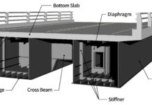
A prime illustration of this lies in the horizontal plane of interaction between precast concrete girders and cast-in-place concrete bridge decks. The composite behaviour exhibited by the girder and deck, which ultimately dictates the bridge’s stiffness and strength, is contingent upon the interface’s capacity to effectively transmit shear forces. In essence, the transfer of shear forces from the deck to the girders plays a crucial role in determining the structure’s load-carrying capacity.
Mechanism of Shear Transfer
The mechanisms governing shear stress transfer can be broadly categorized into three main contributors:
1. Interlock between roughened surfaces (shear – friction): Intentional surface irregularities, often achieved through sandblasting or texturing, create mechanical interlock between the concrete layers. This interlock resists relative movement under shear, contributing to stress transfer.
2. Dowel action of reinforcement: Steel bars embedded in the concrete, particularly shear connectors like headed studs, act as dowels traversing the interface. When subjected to shear, these dowels experience tension and compression, contributing to interface resistance.
3. Adhesion: The inherent bond between the concrete layers, influenced by factors like material properties, curing conditions, and surface cleanliness, also plays a role in shear transfer.
The critical mechanism of shear transfer across concrete-to-concrete interfaces in reinforced concrete (RC) structures can be elucidated through the saw-tooth model (Figure 1). This model visualizes the interaction between concrete surfaces under shear force.

When subjected to shear, a horizontal displacement (h) occurs between the concrete layers. This relative movement triggers a vertical displacement (v) due to interlock between the roughened surfaces. This vertical displacement, in turn, induces tension in the reinforcement crossing the interface. The generated tension translates into a clamping force, enhancing frictional resistance along the interface. Additionally, cohesion, representing the intrinsic bonding force between the concrete surfaces, contributes to shear resistance.
The contribution of each mechanism varies with the applied load. At low loads, cohesion predominates, effectively resisting the shear force. However, as the load increases, cracks develop within the interface, compromising the cohesive bond. Consequently, the burden of shear resistance shifts to a combination of shear-friction and dowel action.
Shear-friction originates from the interaction between the clamping force and the frictional resistance along the interface. Essentially, the clamping force, generated by the tensioned reinforcement, presses the concrete surfaces together, creating friction that opposes the relative movement.
Dowel action stems from the direct shear resistance offered by the steel bars traversing the interface. These bars experience tension and compression under shear, contributing to the overall interface resistance.
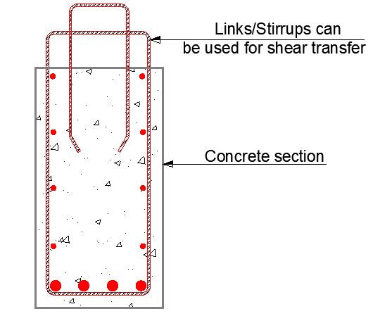
In essence, the shear transfer mechanism in RC interfaces operates as a dynamic interplay between cohesion, shear-friction, and dowel action. Understanding the individual contributions and their interplay under varying load conditions is crucial for ensuring the structural integrity and performance of RC structures.
Factors Affecting Shear Transfer Capacity
The magnitude of shear transfer capacity is not a static value but depends on several factors, including:
- Interface characteristics: Surface roughness, presence of contaminants, and potential shrinkage gaps all influence the effectiveness of mechanical interlock and adhesion.
- Concrete properties: Strength, age, and moisture content of the concrete layers affect their bond characteristics and susceptibility to cracking.
- Reinforcement details: Type, spacing, and embedment depth of dowel bars significantly impact their contribution to shear transfer.
- Loading conditions: Sustained or cyclic loading, along with the magnitude and distribution of shear forces, influence the interface’s response.
Shear Transfer According to the Eurocodes
Section 6.2.5 of Eurocode 2 (EC2) defines the methodology for evaluating the shear capacity of interfaces between concretes cast at different times. This approach considers the combined contributions of cohesion and friction to interface resistance.
The shear stress at the interface is calculated by the difference of the longitudinal internal force ΔF (tension or compression) in the examined part of the cross-section separated by the interface. The part of the longitudinal force (compressive or tensile) that is located within the new concrete is expressed by the coefficient β.
Following a stress-based approach, the equation provided within the code expresses the shear stress capacity (VRd,i) as a function of;
vRdi = c⋅fctd + μ⋅σn + ρ⋅fyd ⋅ (μ⋅sinα + cosα) ≤ vRdi,max
where;
fctd is the design tensile strength of concrete;
σn is the stress per unit area caused by the minimum external normal force across the interface that can act simultaneously with the shear force, positive for compression, such that σn ≤ 0.6fcd;
fyd is the design yield strength of reinforcement, not more than 600 MPa;
ρ is the reinforcement ratio (As/Ac);
α is the angle between concrete interface and interface reinforcement;
c and μ are factors that depend on the roughness of the interface; values are listed in Table 2.
| Condition | c | μ |
| Very smooth interface roughness condition; A surface cast against steel, plastic or specially prepared wooden molds. | 0.025 | 0.5 |
| Smooth interface roughness condition; A slip-formed or extruded surface, or a free surface left without further treatment after vibration. | 0.2 | 0.6 |
| Rough interface condition; A surface with at least 3 mm roughness at about 40 mm spacing, achieved by ranking, exposing of aggregate or other methods giving an equivalent behavior | 0.4 | 0.7 |
| Indented interface condition; A surface with indentations complying with more than 3 mm roughness and also depth of groove should be more than 5 mm and the width of the groove should be more than 10 times its depth | 0.5 | 0.9 |
vRdi,max = 0.5 ⋅ ν ⋅ fcd
Where ν is the strength reduction factor for shear design in accordance with EN1992-1-1 §6.2.2(6).
ν = 0.6 ⋅ (1 – fck / 250 MPa)
fcd is the design compressive strength of the concrete
fck is the characteristic compressive strength of the concrete after 28 days
Design Example
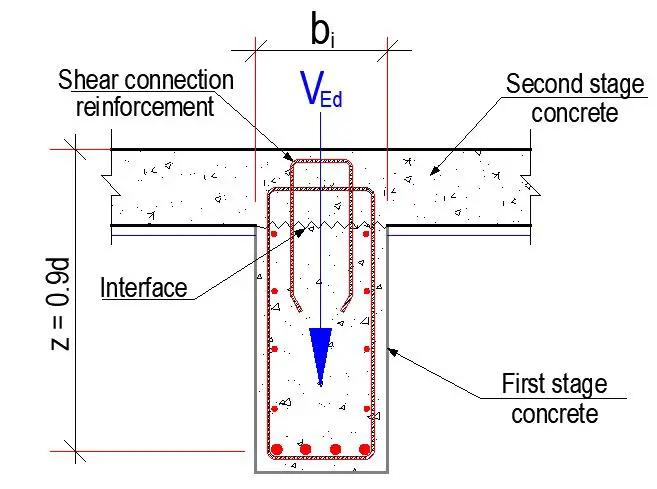
Design the shear transfer between a girder of 600 mm width to a slab topping of 250 mm thickness. The shear force at the section is 655 kN and the interface between the old and new concrete is rough. Take the lever arm for the internal forces of composite section z = 0.9m. fck = 30 MPa, fyk = 500 MPa.
Solution
Applied shear stress at the interface
By assuming a constant lever arm of internal forces z in the examined infinitesimal segment dx then the corresponding difference of longitudinal force ΔF is:
ΔF = β(M + dM) / z – βM/z = βdM/z
Where dM is the infinitesimal change of the bending moment. In the calculation above the variation of the normal force N is not considered significant. The shear stress at the interface v is calculated by dividing the difference of longitudinal force ΔF by the width of the interface bi and the assumed infinitesimal length dx. According to fundamental mechanics, the shear force is calculated as the derivative of the bending moment V = dM / dx.
The aforementioned analysis leads to the design value of the shear stress at the interface vEdi as given by EN1992-1-1 §6.2.5(1) equation (6.24):
vEdi = β⋅VEd / (z⋅bi) = (1.0 × 655 × 103) / (900 × 600) = 1.213 MPa
Shear strength of the interface
c = 0.400 and μ = 0.700 (for rough surfaces)
The coefficient for concrete cohesion c should be reduced for the case of fatigue or dynamic loads. In general according to EN1992-1-1 §6.2.5(5) under fatigue or dynamic loads, the values for c should be halved. Specifically for bridges, according to EN1992-2 §6.2.5(105) under fatigue and dynamic loads a value of 0.0 should be considered for c. Moreover when the normal stress σn is tensile (i.e. negative) then a value of 0.0 should be considered for c in accordance with EN1992-1-1 §6.2.5(1).
For the examined case the adjustment factor applied to the value of c is 0.40. The adjusted value of the coefficient is c = 0.40 × 0.400 = 0.160.
Maximum shear strength that can be transferred at the interface
The maximum value of the design shear resistance vRdi,max of the interface is limited by the compressive strength of the concrete struts as specified in EN1992-1-1 §6.2.5(1):
vRdi,max = 0.5νfcd
ν = 0.6 ⋅ (1 – fck / 250 MPa) = 0.6 × (1 – 30.00 MPa / 250 MPa) = 0.528
fcd = αcc ⋅ fck / γC = (1.00 × 30.00) / 1.50 = 20.00 MPa
Therefore the maximum value of the design shear resistance vRdi,max is calculated as:
vRdi,max = 0.5νfcd = (0.5 × 0.528 × 20.00 MPa) = 5.280 MPa
For the examined case the applied shear stress on the interface vEdi = 1.213 MPa does not exceed the maximum shear stress capacity of concrete vRdi,max = 5.280 MPa. The corresponding utilization factor is u = 0.23 ≤ 1.0 ⇒ ok.
Calculation of required shear connection reinforcement
The calculation of the required shear connection reinforcement ratio ρ can be performed by solving EN1992-1-1 equation (6.25) for ρ. The equation that defines the design shear resistance of the interface is:
vRdi = c⋅fctd + μ⋅σn + ρ⋅fyd ⋅ (μ⋅sinα + cosα) ≤ vRdi,max
The values of the trigonometric functions when the shear connection reinforcement forms angle α = 90.0 ° with the interface plane are sinα = 1.0 and cosα = 0. The value of the design tensile strength of concrete fctd is calculated as specified in EN1992-1-1 §3.1.6(2)P:
fctd = αct ⋅ fctk,0.05 / γC = (1.00 × 2.03 MPa) / 1.50 = 1.35 MPa
where fctk,0.05 = 0.7 × fctm = 0.7 × 2.90 MPa = 2.03 MPa is the 5% fractile of the tensile strength of concrete as specified in EN1992-1-1 Table 3.1.
The value of the design yield strength of reinforcement steel fyd is calculated as specified in EN1992-1-1 §3.2:
fyd = fyk / γS = 500/1.15 = 434.8 MPa
The required shear connection reinforcement is calculated when vEdi = vRdi. Provided that vRdi ≤ vRdi,max the aforementioned equation can be solved for the required ratio ρ of the shear connection reinforcement:
σn = 0
ρ = (vEdi – c ⋅ fctd – μ ⋅ σn) / [fyd ⋅ (μ⋅sinα + cosα) ]
(vEdi – c ⋅ fctd – μ ⋅ σn) = 1.213 – (0.16 × 1.35) – 0 = 0.997
[fyd ⋅ (μ⋅sinα + cosα) ] = 434.8 × (0.7 × 1.0 + 0) = 304.36
ρ = 0.997/304.36 = 0.003275
The corresponding required shear connection reinforcement per m length of the interface area is:
Width of area = 600 mm
Length of area (per metre run) = 1000 mm
As = ρ × 1000 mm × 600 mm = 1965 mm2/m
Therefore provide 4legs of H12 @200 mm c/c spacing (Asprov = 2260 mm2/m)
Conclusion
In conclusion, shear transfer in the interface of RC members serves as a critical mechanism for structural integrity. Recognizing the contributing factors, their interactions, and the limitations of current design approaches is essential for ensuring the safety and reliability of such structures. Ongoing research efforts aimed at refining analytical models and leveraging advanced experimental techniques hold promise for advancing our understanding and design capabilities, ultimately leading to safer and more efficient RC structures

