The design and construction of building structures must adhere to fire resistance performance requirements stipulated within the Building Regulations. When exposed to intense heat, concrete undergoes complex physical and chemical transformations.
Initially, the surface loses moisture, followed by spalling (explosive cracking) as internal moisture vaporizes. As temperatures rise further, the calcium silicate hydrates, the binding agents within the concrete, decompose, leading to a significant loss in strength and stiffness.
Steel reinforcement is also significantly affected by fire. Its tensile strength diminishes rapidly at elevated temperatures, increasing the risk of failure. Steel reinforcement suffers strength degradation with a 50% loss occurring around 560°C and a 75% loss at approximately 700°C. Therefore, adequate concrete cover is essential to delay the time it takes for the reinforcement to reach temperatures triggering structural failure.
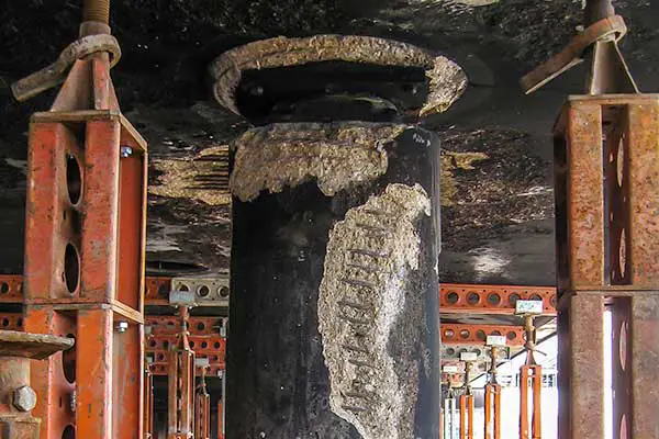
During a fire event, the primary structural concerns pertain to the floor construction directly above the flames and any supporting columns or walls. The fire resistance of the floor elements, comprising beams, ribs, and slabs, hinges critically on the thermal protection provided to the bottom reinforcement.
To ensure stability during a fire event, structural elements must exhibit a minimum specified period of fire resistance as determined by standardized testing procedures. The requisite fire resistance period depends on two primary factors:
- Building Purpose Group: The designated purpose group of the building, which categorizes its intended use and occupant occupancy levels, dictates the baseline fire resistance requirements.
- Building Height and Depth: Additionally, the height of the above-ground structure, or alternatively, the depth of a basement relative to the ground level, further influences the mandated fire resistance period. These correlations are detailed in Table 1.
| Purpose group of building | Minimum fire periods (hours) for elements of structure | |||||
| Basement story | Ground or upper story | |||||
| Depth (m) of lowest basement | Height (m) of top floor above ground in building or separated part of a building | |||||
| ≤ 10 | >10 | ≤ 5 | ≤ 18 | ≤ 30 | >30 | |
| Residential Flats and maisonettes | 1.0 | 1.5 | 0.5 | 1.0 | 1.5 | 2.0 |
| Residential dwelling houses | 0.5 | – | 0.5 | 1.0 | – | – |
| Residential (institutional) | 1.0 | 1.5 | 0.5 | 1.0 | 1.5 | 2.0 |
| Other residential | 1.0 | 1.5 | 0.5 | 1.0 | 1.5 | 2.0 |
| Office (not sprinklered) | 1.0 | 1.5 | 0.5 | 1.0 | 1.5 | – |
| Office (sprinklered) | 1.0 | 1.0 | 0.5 | 1.0 | 1.0 | 2.0 |
| Shop and commercial (not sprinklered) | 1.0 | 1.5 | 1.0 | 1.0 | 1.5 | – |
| Shop and commercial (sprinklered) | 1.0 | 1.0 | 0.5 | 1.0 | 1.0 | 2.0 |
| Assembly and recreation (not sprinklered) | 1.0 | 1.5 | 1.0 | 1.0 | 1.5 | – |
| Assembly and recreation (sprinklered) | 1.0 | 1.0 | 0.5 | 1.0 | 1.0 | 2.0 |
| Industrial (not sprinklered) | 1.5 | 2.0 | 1.0 | 1.5 | 2.0 | – |
| Industrial (sprinklered) | 1.0 | 1.5 | 0.5 | 1.0 | 1.5 | 2.0 |
| Storage and other non-residential (not sprinklered) | 1.5 | 2.0 | 1.0 | 1.5 | 2.0 | – |
| Storage and other non-residential (sprinklered) | 1.0 | 1.5 | 0.5 | 1.0 | 1.5 | 2.0 |
Beyond the minimum regulatory requirements, building insurers may impose stricter fire resistance demands for specific scenarios, such as high-value storage facilities, where contents and potential reconstruction costs necessitate extended fire containment.
Fire Resistance Design Approaches in BS 8110
British Standard 8110 (BS 8110) establishes a two-tier framework for fire resistance design:
- Part 1: Simple Recommendations: This section caters to a broad range of applications and provides straightforward recommendations suitable for most common design scenarios.
- Part 2: Detailed Design Methods: For intricate fire resistance considerations, Part 2 offers a more nuanced approach, presenting three distinct design methods:
- Tabulated Data: Predefined tables specify minimum element dimensions and concrete cover thicknesses for various structural members, simplifying selection for typical cases.
- Furnace Testing: Direct fire exposure testing on specific structural components can be conducted to validate or optimize their fire resistance performance.
- Fire Engineering Calculations: Advanced fire engineering analysis methods enable bespoke calculations of component and system behaviour under fire conditions, offering greater flexibility and design customization for complex scenarios.
Importantly, BS 8110 recognizes the influence of section geometry on concrete cover requirements. For beams and ribs, the specified cover thicknesses can be adjusted based on the actual width of the structural member, optimizing material usage and maintaining adequate protection for the embedded reinforcement.
Part 1 of the relevant design standard adopts the same fundamental data as Part 2 for determining fire resistance requirements. However, the presentation format differs in two key aspects:
- Nominal Cover: Instead of tailoring cover thicknesses based on section width, Part 1 specifies a single “nominal cover” value applicable to all reinforcement, inclusive of an allowance for link elements in beams and columns.
- Simplified Values: Unlike Part 2’s dynamic adjustments based on section geometry, Part 1 utilizes fixed cover and dimension values tabulated in Tables 2 and 3 for simplified application in diverse design scenarios.
| Fire period (hours) | Nominal cover (mm) | ||||||
| Beams | Floors | Ribs | Columns | ||||
| Simply supported | Continuous | Simply supported | Continuous | Simply supported | Continuous | ||
| 0.5 | 20 | 20 | 20 | 20 | 20 | 20 | 20 |
| 1.0 | 20 | 20 | 20 | 20 | 20 | 20 | 20 |
| 1.5 | 20 | 20 | 25 | 20 | 35 | 20 | 20 |
| 2.0 | 40 | 30 | 35 | 25 | (45) | 35 | 25 |
| 3.0 | (60) | 40 | (45) | 35 | (55) | 40 | 25 |
| 4.0 | (70) | (50) | (55) | (45) | (65) | (50) | 25 |
Where values are shown in parenthesis, additional measures should be taken to reduce the risk of spalling. For the purpose of assessing a nominal cover for beams and columns, an allowance for links of 10mm has been made to cover the range from 8 mm to 12 mm.
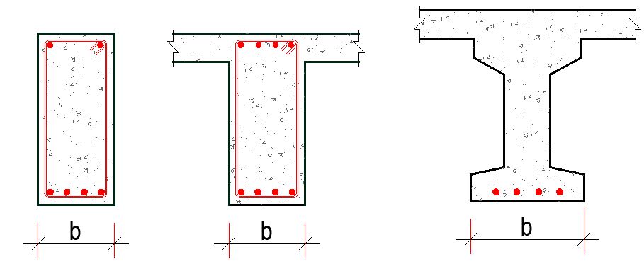

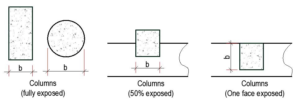
| Fire resistance period (hours) | Minimum beam width (b) mm | Minimum rib width (b) mm | Minimum floor thickness (h) mm | Minimum column width (b) | Minimum wall thickness for reinforcement percentage p | ||||
| Fully exposed (mm) | 50% exposed (mm) | One face exposed (mm) | p < 0.4 (mm) | 0.4 < p < 1.0 (mm) | p > 1.0 (mm) | ||||
| 0.5 | 200 | 125 | 75 | 150 | 125 | 100 | 150 | 100 | 75 |
| 1.0 | 200 | 125 | 95 | 200 | 160 | 120 | 150 | 120 | 75 |
| 1.5 | 200 | 125 | 110 | 250 | 200 | 140 | 175 | 140 | 100 |
| 2.0 | 200 | 125 | 125 | 300 | 200 | 160 | – | 160 | 100 |
| 3.0 | 240 | 150 | 150 | 400 | 300 | 200 | – | 200 | 150 |
| 4.0 | 280 | 175 | 170 | 450 | 350 | 240 | – | 240 | 180 |
The design approach considers the different implications of fire on load-bearing behaviour:
- Simply Supported Spans: For these elements, a 50% strength loss in the bottom reinforcement can be critical, necessitating stricter cover requirements to ensure continued stability.
- Continuous Spans: In this case, some degree of bottom reinforcement strength loss can be tolerated as the top reinforcement retains its full capacity and contributes to load redistribution.
Excessive concrete cover, while enhancing thermal protection, also carries the risk of premature spalling during fire exposure. This phenomenon is particularly concerning for concretes containing aggregates rich in silica. Therefore, finding the optimal balance between adequate cover and minimizing spalling risk becomes crucial for effective fire resistance design.
When exceeding a nominal concrete cover of 40 mm, alternative strategies necessitate consideration. BS 8110 Part 2 details several potential approaches. Primarily, cover reduction is preferred, achieved through supplementary protection elements like applied finishes, false ceilings, or lightweight aggregates (LWA). A final option involves deploying “sacrificial steel,” exceeding necessary reinforcement to accommodate potential fire-induced strength loss.
If exceeding 40 mm remains unavoidable, additional reinforcement via welded steel fabric embedded 20 mm from the concrete surface is permitted. However, significant practical limitations exist, and potential conflict with durability requirements in certain scenarios must be assessed.
Fire Resistance Design Approaches in EN 1992 (Eurocode 2)
The general requirement in Eurocode 2 for the fire design of reinforced concrete structures is that structures should be able to retain their load-bearing function during the required time of fire exposure. Eurocode 2, Part 1-2: Structural fire design, offers three approaches for fire resistance determination: advanced, simplified, and tabular methods.
While tabular methods provide the fastest route for calculating minimum slab dimensions and cover thicknesses, their application is subject to specific limitations. Consulting specialist literature is recommended for further guidance on the intricacies of advanced and simplified methods.
Unlike the other approaches, the tabular method employs the concept of nominal axis distance (a) instead of a minimum cover. This parameter represents the distance from the centre of the primary reinforcing bar to the member’s exposed surface. It is important to note that the value of a is nominal, not a true minimum requirement.
EC 2 also introduces a more adaptable approach to fire safety design, founded on the concept of “load ratio” – the ratio of applied load at the fire limit state to the element’s ambient temperature capacity.
Fire Performance Criteria
Three fundamental performance criteria are established:
- Criterion R: Load bearing function is maintained for the requisite fire resistance duration.
- Criterion I: Average temperature rise across the unexposed surface does not exceed 140 K, and no point on that surface surpasses 180 K, thereby potentially preventing ignition of combustible materials on the protected side of a compartment wall.
- Criterion E: No cracks, holes, or openings allowing flame or hot gas passage from the fire compartment to adjacent unburnt compartments.
For standard fire exposure, members must comply with criteria R, E, and I as follows:
- Load bearing only: Mechanical resistance (criterion R)
- Separation only: Integrity (criterion E) and, optionally, insulation (criterion I)
- Combined load bearing and separation: Criteria R, E, and, optionally, I
Notations like R30, R60, E30, E60, I30, and I60 signify compliance with the respective criteria (R, E, and I) during at least 30 or 60 minutes of standard fire exposure. REI 90 signifies simultaneous compliance with all three criteria for at least 90 minutes, with the most critical criterion governing the classification.
These criteria are evaluated within a structural fire design analysis encompassing the following steps:
- Selection of relevant fire scenarios based on a fire risk assessment.
- Determination of the corresponding design fire, applicable to only one fire compartment at a time.
- Calculation of temperature evolution within structural members, considering fire exposure through facade and roof openings for external members.
- Calculation of the mechanical behaviour of the structure under fire exposure.
Design Based on Tabulated Data
Tabulated data presents minimum cross-sectional dimensions and nominal axis distances for primary reinforcement, accompanied by detailed specifications tailored to each member type. This method offers a validated approach for verifying the fire resistance of individual structural members, providing recognized design solutions for standard fire exposures up to a duration of 240 minutes. A key advantage is the expedited verification of whether dimensions derived from ambient temperature design remain acceptable under fire conditions. The following considerations are pertinent:
- The tabulated values are predicated upon a standard fire exposure as defined by ISO 834.
- Their development rests upon empirical tests, further corroborated by practical experience and theoretical evaluations of test results. The values themselves err on the side of conservatism to ensure safety margins.
- Applicability is limited to normal-weight concrete composed of siliceous aggregates. In beams and slabs utilizing calcareous or lightweight aggregates, a 10% reduction in minimum cross-sectional dimensions is permissible.
- Adhering to tabulated values eliminates the necessity for additional assessments regarding explosive spalling, shear and torsion capacity, and anchorage details.

General rules
1. To ensure compliance with criterion R (load-bearing function) during the specified standard fire resistance, minimum requirements for cross-sectional dimensions and reinforcement axis distances have been established. The tabulated data assume a reference load level of μfi = 0.7.
2. The tables specify minimum concrete cover as the distance “a” between the main reinforcement’s axis and the nearest concrete surface (see Figure 5). These axis distances are nominal values, not requiring tolerance allowances. Note that Eurocode 2, Part 1-1, addressing normal temperature design, defines concrete cover “c” as the distance from the reinforcing bar’s edge to the closest concrete surface. Therefore, for a longitudinal rebar with a diameter φbar, the relationship between “a” and “c” can typically be expressed as a = c + φstirrup + φbar/2, where φstirrup represents the stirrup diameter.
3. Minimum axis distances for reinforcement located within tensile zones of simply supported beams and slabs were calculated using a critical steel temperature (θcr) of 500 °C. This critical temperature signifies the point at which steel yields under the fire-induced steel stress (σs,fi). For prestressing tendons, critical temperatures are assumed to be 400 °C for bars and 350 °C for strands and wires.
Fire Resistance Requirements of Slabs (EC2)
In ensuring acceptable fire resistance for reinforced and prestressed concrete slabs, Table 4 provides minimum thicknesses that satisfy the separation function (Criteria E and I). While thicker floor finishes can enhance separation, load-bearing capacity (Criterion R) can be solely determined by the slab thickness required for design under EN 1992-1-1 if this function is the only concern. This approach streamlines assessment by considering separate functions when necessary and leveraging existing design rules for load-bearing capacity.

Simply supported solid slabs
Table 4 provides minimum values of axis distance to the soffit of simply supported slabs for standard fire resistances of R 30 to R 240. In two-way spanning slabs, a denotes the axis distance of the reinforcement in the lower layer.
| Standard Fire Resistance | Minimum dimensions (mm) | |||
| Slab thickness hs (mm) | Axis distance a | |||
| One way | Two-way ly/lx ≤ 2.0 | Two way ly/lx ≤ 2.0 | ||
| 1 | 2 | 3 | 4 | 5 |
| REI 30 | 60 | 10* | 10* | 10* |
| REI 60 | 80 | 20 | 10* | 15* |
| REI 90 | 100 | 30 | 15* | 20 |
| REI 120 | 120 | 40 | 20 | 25 |
| REI 180 | 150 | 55 | 30 | 40 |
| REI 240 | 175 | 65 | 40 | 50 |
| ly and lx are the spans of a two-way slab (two directions at right angles) where ly is the longer span. For prestressed slabs, the increase of axis distance according to 5.2(5) should be noted. The axis distance (a) in Columns 4 and 5 for two-way slabs relates to slabs supported at all four edges. Otherwise, they should be treated as a one-way spanning slab. * Normally the cover required by EN 1992-1-1 will control. | ||||
The values given in Table 4 (Columns 2 and 4) also apply to one-way or two-way continuous slabs.
Ribbed Slabs
Assessing the fire resistance of ribbed slabs, reinforced or prestressed, follows different paths for one-way and two-way configurations. For one-way slabs, specific provisions for beams, Table 4, columns 2 and 5 for flanges govern.
In contrast, two-way ribbed slabs rely on the values in Tables 5 and 6, alongside additional rules, assuming predominantly uniform loading. These tables cater to simply supported or restrained edge scenarios with varying fire resistance requirements and reinforcement detailing stipulations.
Notably, Table 5 applies to simply supported or one restrained edge cases with fire resistance below REI 180 where specific upper reinforcement arrangements are absent. For slabs with at least one restrained edge, Table 6 takes precedence, and section 5.6.3(3) of EN 1992-1-2 dictates the upper reinforcement detailing across all fire resistance levels.
| Standard fire resistance | Minimum dimensions (mm) | |||
| Possible combinations of widths of ribs bmin and axis distance a | Slab thickness hs and axis distance a in flange | |||
| 1 | 2 | 3 | 4 | 5 |
| REI 30 | bmin = 80 a = 15* | hs = 80 a = 10* | ||
| REI 60 | bmin = 100 a = 35 | 120 25 | ≥200 15* | hs = 80 a = 10* |
| REI 90 | bmin = 120 a = 45 | 160 40 | ≥250 30 | hs = 100 a = 15* |
| REI 120 | bmin = 160 a = 45 | 190 55 | ≥300 40 | hs = 120 a = 20 |
| REI 180 | bmin = 220 a = 75 | 260 70 | ≥410 60 | hs = 150 a = 30 |
| REI 240 | bmin = 280 a = 90 | 350 75 | ≥500 70 | hs = 175 a = 40 |
| asd = a + 10 | ||||
| asd denotes the distance measured between the axis of reinforcement and lateral surface of the rib exposed to fire. *Normally the cover required by EN 1992-1-1 will control | ||||
| Standard fire resistance | Minimum dimensions (mm) | |||
| Possible combinations of widths of ribs bmin and axis distance a | Slab thickness hs and axis distance a in flange | |||
| 1 | 2 | 3 | 4 | 5 |
| REI 30 | bmin = 80 a = 10* | hs = 80 a = 10* | ||
| REI 60 | bmin = 100 a = 25 | 120 15* | ≥200 10* | hs = 80 a = 10* |
| REI 90 | bmin = 120 a = 35 | 160 25 | ≥250 15* | hs = 100 a = 15 |
| REI 120 | bmin = 160 a = 45 | 190 40 | ≥300 30 | hs = 120 a = 20 |
| REI 180 | bmin = 310 a = 60 | 600 50 | hs = 150 a = 30 | |
| REI 240 | bmin = 450 a = 70 | 700 60 | hs = 175 a = 40 | |
| asd = a + 10 | ||||
| asd denotes the distance measured between the axis of reinforcement and lateral surface of the rib exposed to fire. *Normally the cover required by EN 1992-1-1 will control | ||||
Flat Slabs
Flat slabs exhibiting minimal moment redistribution (less than 15% in accordance with EN 1992-1-1, Section 5) may be assessed for fire resistance utilizing the same principles as one-way slabs, employing axis distances and minimum thicknesses outlined in Table 7. However, for fire resistance ratings of REI 90 or higher, additional measures are mandated.
At least 20% of the top reinforcement spanning intermediate supports, as prescribed by EN 1992-1-1, must be continuous across the entire slab and positioned within the column strip. Furthermore, no reduction in the minimum slab thickness, regardless of floor finishes, is permitted. In essence, elevated fire resistance demands necessitate stricter continuity and thickness requirements for flat slabs with limited moment redistribution.
| Standard fire resistance | Minimum dimensions (mm) | |
| Slab thickness hs | Axis distance a | |
| 1 | 2 | 3 |
| REI 30 | 150 | 10* |
| REI 60 | 180 | 15* |
| REI 90 | 200 | 25 |
| REI 120 | 200 | 35 |
| REI 180 | 200 | 45 |
| REI 240 | 200 | 50 |
| *Normally the cover required by EN 1992-1-1 will control | ||
Fire Resistance Requirement of Beams
The fire resistance of reinforced and prestressed concrete beams can be confidently assessed using the data presented in Tables 8 and 9. These tables apply specifically to beams experiencing fire exposure on three sides, assuming the top surface is adequately insulated by overlying slabs or other elements throughout the designated fire resistance period. For scenarios where fire exposure occurs on all sides of the beam, additional considerations outlined in clause 4.6.5 of EN 1992 1-2 must be taken into account.

Simply supported beams
Table 8 provides minimum values of axis distance to the soffit and sides of simply supported beams together with minimum values of the width of beam, for standard fire resistances of R 30 to R 240.
| Standard fire resistance | Minimum dimensions (mm) | ||||||
| Possible combinations of a and bmin where a is the average axis distance and bmin is the width of the beam | Web thickness bw | ||||||
| Class WA | Class WB | Class WC | |||||
| 1 | 2 | 3 | 4 | 5 | 6 | 7 | 8 |
| R30 | bmin = 80 a = 25 | 120 20 | 160 15* | 200 15* | 80 | 80 | 80 |
| R60 | bmin = 120 a = 40 | 160 35 | 200 30 | 300 25 | 100 | 80 | 100 |
| R90 | bmin = 150 a = 55 | 200 45 | 300 40 | 400 35 | 110 | 100 | 100 |
| R120 | bmin = 200 a = 65 | 240 60 | 300 55 | 500 50 | 130 | 120 | 120 |
| R180 | bmin = 240 a = 80 | 300 70 | 400 65 | 600 60 | 150 | 150 | 140 |
| R240 | bmin = 280 a = 90 | 350 80 | 500 75 | 700 70 | 170 | 170 | 160 |
| asd = a + 10 | |||||||
| asd is the axis distance to the side of beam for the corner bars (or tendon or wire) of beams with only one layer of reinforcement. For values of bmin greater than that given in Column 4 no increase of asd is required. * Normally the cover required by EN 1992-1-1 will control. | |||||||
Continuous Beams
For continuous beams with standard fire resistance ratings ranging from R 30 to R 240, Table 9 specifies minimum axis distances to the soffit and sides, along with minimum beam widths. However, the validity of this data hinges on two crucial conditions:
- Detailed Design Compliance: All prescribed detailing rules outlined in the source material must be meticulously followed.
- Moment Redistribution Limit: The redistribution of bending moments at normal temperatures must not exceed 15%. Beyond this threshold, the beams must be treated as simply supported for fire resistance assessment purposes.
| Standard fire resistance | Minimum dimensions (mm) | ||||||
| Possible combinations of a and bmin where a is the average axis distance and bmin is the width of the beam | Web thickness bw | ||||||
| Class WA | Class WB | Class WC | |||||
| 1 | 2 | 3 | 4 | 5 | 6 | 7 | 8 |
| R30 | bmin = 80 a = 15* | 160 12* | 80 | 80 | 80 | ||
| R60 | bmin = 120 a = 25 | 200 12* | 100 | 80 | 100 | ||
| R90 | bmin = 150 a = 35 | 250 25 | 110 | 100 | 100 | ||
| R120 | bmin = 200 a = 45 | 300 35 | 450 35 | 500 30 | 130 | 120 | 120 |
| R180 | bmin = 240 a = 60 | 400 50 | 500 50 | 600 40 | 150 | 150 | 140 |
| R240 | bmin = 280 a = 75 | 500 60 | 650 60 | 700 50 | 170 | 170 | 160 |
| asd = a + 10 | |||||||
| asd is the axis distance to the side of beam for the corner bars (or tendon or wire) of beams with only one layer of reinforcement. For values of bmin greater than that given in Column 4 no increase of asd is required. * Normally the cover required by EN 1992-1-1 will control. | |||||||
Fire Resistance Requirement of Columns
The fire resistance of reinforced and prestressed concrete columns in braced structures primarily subjected to compression can be evaluated through two methods (Method A and Method B). Method A offers a streamlined approach, relying on the data in Table 10 and adhering to specific accompanying rules. This method ensures adequate fire resistance under these conditions, enabling efficient structural design in fire-resistant buildings.
- effective length of the column (for definition see EN 1992-1-1 Section 5) under fire conditions: lO,fi ≤ 3 m
- first-order eccentricity under fire conditions: e = MOEd,fi / NOEd,fi ≤ emax
- amount of reinforcement: As < 0.04 Ac
Degree of utilization in the fire situation, μfi, has been introduced in Table 10. This accounts for the load combinations, compressive strength of the column and bending including second-order effects.
μfi = NEd.fi/NRd
where;
NEd,fi is the design axial load in the fire situation,
NRd is the design resistance of the column at normal temperature conditions
NRd is calculated according to EN 1992-1-1 with Ym for normal temperature design, including second-order effects and an initial eccentricity equal to the eccentricity of NEd,fi.
| Standard fire resistance | Minimum dimensions (mm) Column width bmin/axis distance a of the main bars | |||
| Exposed on more than one side | Exposed on one side | |||
| μfi = 0.2 | μfi = 0.5 | μfi = 0.7 | μfi = 0.7 | |
| 1 | 2 | 3 | 4 | 5 |
| R 30 | 200/25 | 200/25 | 200/32 300/27 | 155/25 |
| R 60 | 200/25 | 200/36 300/31 | 250/46 350/40 | 155/25 |
| R 90 | 200/31 300/25 | 300/45 400/38 | 350/53 450/40** | 155/25 |
| R 120 | 250/40 350/35 | 350/45** 450/40** | 350/57** 450/51** | 175/35 |
| R 180 | 350/45** | 350/63** | 450/70** | 230/55 |
| R 240 | 350/61** | 450/75** | – | 295/70 |
| ** Minimum 8 bars | ||||
Fire Resistance Requirements of Load Bearing Walls
Adequate fire resistance of load-bearing reinforced concrete walls may be assumed if the data given in Table 11 and the following rules are applied. The minimum wall thickness values given in Table 11 may also be used for plain concrete walls (see EN 1992-1-1, Section 12).
| Standard Fire Resistance | Minimum dimensions (mm) | |||
| μfi = 0.35 | μfi = 0.7 | |||
| Wall exposed on one side | Wall exposed on two sides | Wall exposed on one side | Wall exposed on two sides | |
| 1 | 2 | 3 | 4 | 5 |
| REI 30 | 100/10* | 120/10* | 120/10* | 120/10* |
| REI 60 | 110/10* | 120/10* | 130/10* | 140/10* |
| REI 90 | 120/20* | 140/10* | 140/25 | 170/25 |
| REI 120 | 150/25* | 160/25 | 160/35 | 220/35 |
| REI 180 | 180/40 | 200/45 | 210/50 | 270/55 |
| REI 240 | 230/55 | 250/55 | 270/60 | 350/60 |
| * Normally the cover required by EN 1992-1-1 will control. | ||||
Conclusion
Designing for fire resistance in reinforced concrete structures requires a delicate balance between minimizing material usage and ensuring adequate structural integrity during a fire event. This can be achieved by utilizing minimum concrete covers and dimensions prescribed in codes and guidelines like Eurocode 2 part 2.
These minimums safeguard the internal reinforcement from excessive temperature rise, protecting its strength and maintaining load-bearing capacity. However, blindly applying these minimums is insufficient. Fire resistance design also involves factors like:
- Member type and loading: Different elements, like beams, columns, and slabs, experience varying heat transfer and stress under fire. Specific rules tailored to each element dictate minimum covers and dimensions to ensure stability.
- Fire exposure conditions: The duration and intensity of the fire exposure significantly impact required member sizes and cover thicknesses.
- Concrete properties: High-strength concrete offers improved fire resistance compared to normal-strength concrete, allowing for potentially thinner sections due to its enhanced thermal insulation.
Optimizing fire resistance design with minimum covers and dimensions necessitates a holistic approach, considering element type, exposure conditions, and material properties. By applying code provisions and understanding the underlying thermal and structural behaviour, engineers can create fire-resistant concrete structures while minimizing material consumption and cost.


