Cracking is normal in reinforced concrete structures subjected to bending, shear, twisting, axial tension, and restraint from movement. This is mainly due to the low tensile strength of concrete. Cracking is usually a serviceability limit state problem, but apart from ruining the appearance of the concrete surface, it also posses durability issues, and leakage problem in water retaining structures.
Cracking is assumed to occur in a concrete section when the restraint strain exceeds the tensile strength capacity of the concrete. This means that for cracking to occur, some part or the whole of the concrete section must be in tension. Crackwidth in concrete is predicted by multiplying crack inducing strain (strain dissipated by the occurence of cracking) by the crack spacing.
The crack inducing strain due to flexure (bending) is given in expression 7.9 of EN 1992-1-1 as;
where;
εsm = mean strain in reinforcement.
εcm = mean strain in the concrete between cracks.
σs = stress in the reinforcement based on cracked section properties under quasi permanent load combination
αe = modular ratio, Es/Ecm (generally a value of 7 may be used.)
kt = 0.6 for short term loading and
0.4 for long term loading.
fct,eff = fctm at 3 days and/or 28 days.
ρp,eff = As/Ac,eff (this is calculated for each face)
Where; As = area of reinforcement provided, mm2
Ac,eff = Area of concrete in tension whose depth is:
min[0.5h , 2.5(c + 0.5ϕ) , (h – x)/3] for each face of a wall
where;
h = thickness of wall
c = nominal cover
ϕ = bar diameter
x = depth to neutral axis
d = effective depth.
Es = elastic modulus for reinforcement = 200,000 MPa
Solved Example
Calculate the crackwidth due to externally applied load on a 200 mm thick slab with the following data;
Design serviceability bending moment = 14.96 kNm/m
Area of tension reinforcement provided at ultimate limit state As1 = H12@200 c/c (Asprov = 565 mm2/m)
Concrete cover = 25 mm
Effective depth d = 200 – 12/2 – 25 = 169 mm
Solution
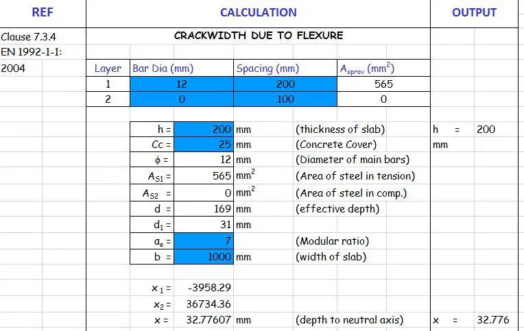
STEP 1: Calculate the depth to the neutral axis of the section
The full procedure on how to calculate the depth of neutral axis of slabs and walls can be obtained by downloading our textbook on Design of Swimming Pool and Underground Water Tank, HERE
Otherwise, you can download our fully functional EXCEL Spreadsheet for a cheaper price (NGN 1000 only) HERE
From excel spreadsheet, x = 32.77 mm
STEP 2: Calculate the compressive stress in concrete
1000 × 32.77 × 0.5fc (169 – 32.77/3) = 14.96 × 10⁶
On solving; fc = 5.78 Mpa
STEP 3: Calculate the tensile stress in steel
7 × 5.78 × (169 – 32.77)/32.77 = 168.19 Mpa
STEP 4: Calculate the area of concrete in tension
Ac,eff = Area of concrete in tension whose depth is:
min[0.5h , 2.5(c + 0.5ϕ) , (h – x)/3] = min[100, 77.5, 55.74]mm = 55.74 mm
ρp,eff = 565/(55.74 × 1000) = 0.0101
STEP 5: Calculate the crack inducing strain in the section
(εsm – εcm) = [σs – kt(fct,eff/ρp,eff)(1 + αeρp,eff)]/Es
Note that fct,eff is the mean tensile strength of the concrete at 28 days = 2.21 Mpa for C20/25
(εsm – εcm) = [168.19 – 0.4(2.21/0.0101)(1 + 7 × 0.0101)]/200000
(εsm – εcm) = (168.19 – 93.712)/200000 = 372.386 × 10⁻⁶
372.386 × 10⁻⁶ < 0.6 σs/Es (504.57 × 10⁻⁶)
Therefore take (εsm – εcm) = 504.57 × 10⁻⁶
STEP 6: Calculate the maximum crack spacing
Sr,max = 3.4c + 0.425(k1 k2φ/ ρp,eff)
Take k1 = 0.8 (high bond bars, EN 1992)
k2 = 0.5 (for bending)
Sr,max = 3.4(25) + 0.425 × (0.8 × 0.5 × 12)/0.0101 = 286.98 mm
STEP 7: Calculate the crackwidth
Actual crackwidth wk = (εsm – εcm) × Sr,max = 504.57 × 10-6 × 286.98 mm = 0.14 mm
0.14 mm < 0.3 mm (Therefore crackwidth due to bending is very ok for the floor slab)
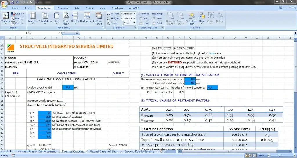
At Structville Integrated Services Limited, we have developed an EXCEL SPREADSHEET that can take care of the following calculations;
(1) Design of floor slabs
(2) Calculation of neutral axis (both for singly and doubly reinforced sections)
(3) Calculation of minimum area of reinforcement
(4) Calculation of early and long term thermal cracking
(5) Calculation of cracking due to loading
A screenshot from the excel spreadsheet is given below;
To download the excel spreadsheet (restricted version), click HERE
To obtain the fully functional excel spreadsheet for NGN 1000 only, click HERE


• Great Blog… The information you shared is very effective for learners I have got some important suggestions from it, Keep Sharing such a nice blog.Fabrication Drawings preparation in UK
MEP F modelling in UK
Interference Analysis in UK
COBie adaptation in UK