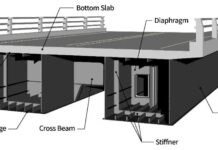
In the design of bridges, environmental actions such as wind, snow, and temperature should also be considered alongside traffic actions. In this article, we are going to show how to apply wind action on bridge decks according to the procedures described in EN 1991-1-4. The specifications in this code apply to bridges of constant cross-section with one or more spans. Different bridge deck sections are permitted such as mono-cell box sections, closed box sections, beam and slab deck systems, etc (see Fig 8.1 of EN 1991-1-4).
In EN 1991-1-4, wind load on bridge decks are considered to be coming from the longitudinal (y-direction) or from transverse (x-direction) axes, and these actions generate stresses in the x,y,z directions of the bridge deck (see Figure 1). During analysis, you can only consider the wind coming in one direction only (either x or y direction) for each load combination.
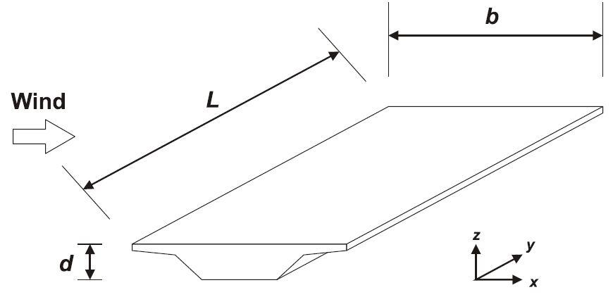
Wind forces acting on a bridge deck
Wind forces acting in the x-direction of a bridge deck is given by the simplified equation (1);
Fwk = 0.5ρVb2C.Aref,x —– (1)
Where;
ρ = density of air = 1.25 kg/m3
Vb = basic wind speed of the site
C = Wind load factor for the bridge
Aref,x = Reference area
In the absence of traffic, the reference area Aref,x should take into account the total height d of projection on a vertical plane of all beams, including the part of one cornice or footway or ballasted track projecting over the front main girder, plus the sum d1 of solid parapets, noise barriers, windshields, and open safety barriers installed on the bridge. In the case of truss girders, the total height d of the projection on a vertical plane of all truss members should be considered.
In the presence of traffic, the reference area Aref,x should be assumed as the larger between the area evaluated considering the absence of traffic, and the area obtained taking into account the presence f traffic. For road bridges, the lateral surface of vehicles exposed to wind is represented by a rectangular area 2m in height starting from the carriageway level.
The wind load factor C is given by equation (2);
C = cecf,x —–(2)
Where ce is the exposure coefficient for kinetic pressure and cf,x is the force coefficient which is the drag coefficient without free end flow. The exposure coefficient can be evaluated by considering a reference height ze given by the distance from the lowest point of the ground and the center of the bridge deck disregarding additional parts, parapets, barriers, etc.
For bridges with solid parapets and/or solid barriers and/or traffic, the force coefficient cf,x can be determined using equation (3);
cf,x = min {2.4; max[2.5 – 0.3(b/dtot); 1.3]} —- (3)
Where b is the total width of the bridge and dtot is the height considered in the evaluation of Aref,x = dtot.L
From the above considerations, equation (1) can also be given as equation (4);
Fwk = qp(ze)Cf,x.Aref,x —– (4)
Analysis Example
Evaluate the wind load on the bridge deck with the profile shown in Figure 2. The bottom of the bridge deck is 7m above the ground (see Figure 3), and it is located in a category III area.
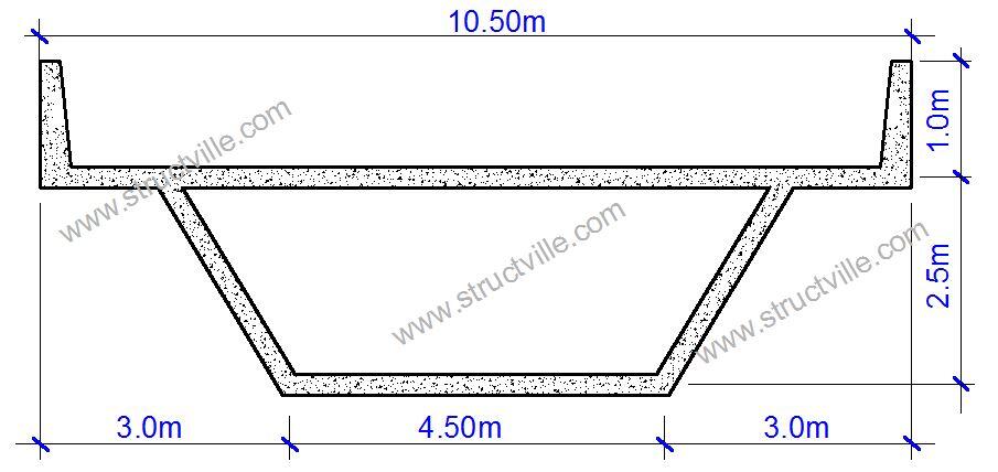

We will therefore take our reference height ze = 7.0 + 1.25 = 8.25 m
For the area under consideration, let the basic wind velocity Vb,0 = 40 m/s.
Therefore;
Vb = Cdir . Cseason . Vb,0 = 1.0 × 1.0 × 30 = 40 m/s
The mean wind velocity Vm(z) at a height z above the terrain depends on the terrain roughness and orography, and on the basic wind velocity, Vb, and should be determined using the expression below;
Vm(z) = cr(z). co(z).Vb
Where;
cr(z) is the roughness factor (defined below)
co(z) is the orography factor often taken as 1.0
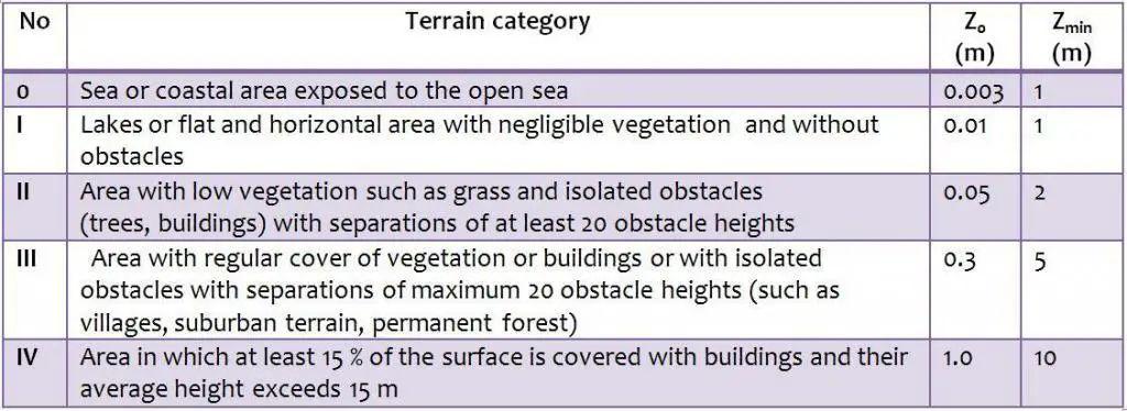
The terrain roughness factor accounts for the variability of the mean wind velocity at the site of the structure due to the height above the ground level and the ground roughness of the terrain upwind of the structure in the wind direction considered. Terrain categories and parameters are shown in Table 1. We will assume that the tank support we are designing is located in an area that can be described as Category III.
Table 1: Terrain Categories and parameters (Table 4.1 EN 1991-1-4:2005)
cr(z) = kr. In (z/z0) for zmin ≤ z ≤ zmax
cr(z) = cr.(zmin) for z ≤ zmin
Where:
Z0 is the roughness length
Kr is the terrain factor depending on the roughness length Z0 calculated using
Kr = 0.19 (Z0/Z0,II)0.07
Where:
Z0,II = 0.05 m (terrain category II)
Zmin is the minimum height
Zmax is to be taken as 200 m
kr = 0.19 (0.3/0.05)0.07= 0.215
cr(z) = kr. In (z/z0)
cr(8.5 m) = 0.215 × In(8.5/0.3) = 0.605
Therefore;
Vm(8.5 m) = cr(z). co(z).Vb = 0.605 × 1.0 × 40 = 24.2 m/s
Wind turbulence
The turbulence intensity Iv(z) at height z is defined as the standard deviation of the turbulence divided by the mean wind velocity. The recommended rules for the determination of Iv(z) are given in the expressions below;
Iv(z) = σv/Vm = k1/[c0(z).In (z/z0)] for zmin ≤ z ≤ zmax
Iv(z) = Iv.(zmin) for z ≤ zmin
Where:
k1 is the turbulence factor of which the value is provided in the National Annex but the recommended value is 1.0
Co is the orography factor described above
Z0 is the roughness length described above.
Iv(8.5 m) = σv/Vm = k1/[c0(z).In (z/z0)] = 1/[1 × In(8.5/0.3)] = 0.299
Peak Velocity Pressure
The peak velocity pressure qp(z) at height z is given by the expression below;
qp(z) = [1 + 7.Iv(z)] 0.5ρVm2 (z)= ce(z).qb
qp(8.5 m) = [1 + 7(0.299)] × 0.5 × 1.25 × 24.22 = 1132.115 N/m2 = 1.132 kN/m2
From equation (4);
Fwk = qp(ze)Cf,x.Aref,x
From Figure 2, we can verify that dtot = 2.5 m + 1.0 m = 3.5 m
b = 10.5 m
cf,x = min {2.4; max[2.5 – 0.3(b/dtot); 1.3]} = min {2.4; max[2.5 – 0.3(10.5/3.5)]; 1.3} = min {2.4; max[1.6; 1.3]}
The minimum value of 1.3 recommended is always deemed unsafe sided, therefore take cf,x = 1.6
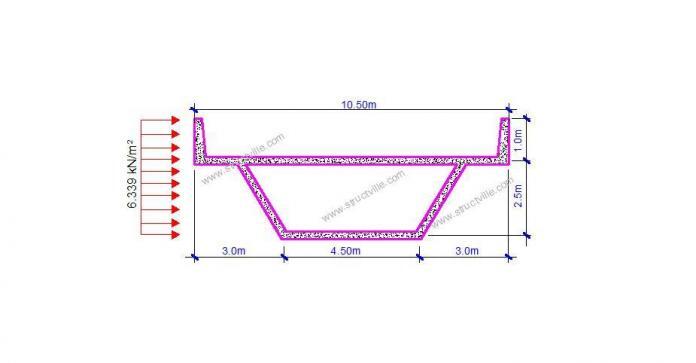
Fwk = 1.132 x 1.6 x 3.5 = 6.3392 kN/m

Thank you for visiting Structville today and God bless you.






Good morning Mr Ubani Obinna
Nice to know about your experience in civil Engineering experience we are anticipated to get some project in West Africa construction of LIG and MIG housing project and if we need any support shall I contact you and if you are willing please share your contact details.
With Kind Regards
Thank you. You can always reach me by sending a mail to ubani@structville.com
Interesting.
I found your blog on Google. Good Job!
Thanks a lot for this calculation, it is amazing.
Thanks for sharing.
Why you did not show the reference area calculation? It says many things in the regulation and its confusing. This example should show me what to consider or not in A (ref) calculation.