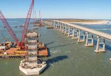
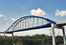
Composite box girders can be an attractive option for medium-span highway bridges. They offer an aesthetically pleasing appearance and speedy construction procedures for bridges. The design and construction techniques already popular for the I-beam form of composite bridges can be used to produce box girder structures.
Composite bridges are structures that combine materials such as steel, concrete, timber or masonry in any combination. In this context, however, composite construction is usually taken to mean either steel and in-situ concrete construction or precast concrete and in-situ concrete bridges. In composite box girder bridges, it is generally accepted that replacing concrete webs with steel will lead to a significant reduction in the weight of the structure.
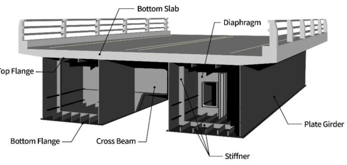
The boxes may be complete steel boxes with an overlay slab, or an open box where the concrete slab closes the top of the box. The use of the open steel box section allows the reintroduction of a bottom concrete compression flange at hogging moment regions by in-filling over supports giving a doubly composite section. This design concept can be used for spans ranging from about 45 m to 100 m.
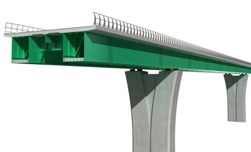
Box girder bridge structures have much greater torsional stiffness than I-beam structures. This feature differentiates their behaviour. The prime effect this has on global bending behaviour is to share the vertical shear more equally between the web planes.
This guide assumes that spans are greater than 45 meters and that the position of supports is largely determined by physical constraints, at least for the major span. However, the bridge may consist of successive spans over land, and the designer may have the freedom to vary span lengths. The selection of a span length will require consideration of the costs of both sub- and super-structure, and a balance will have to be struck for overall economy. The foundation conditions and their consequent cost strongly influence this balance.
Why Composite Box Girders?
According to The Steel Construction Institute (SCI, 2004), box girder bridges and I-beam bridges require approximately the same weight of steel. However, it has been discovered that composite box girders can be optimized to make the best use of their advantages, which can lead to slightly less steel usage. Deck slab thickness is normally similar for both forms of construction. With box girders, torsionally stiff beams can often reduce the number of bearings or support positions, leading to a more slender sub-structure.
Moreover, curvature is more easily achieved with box girders. Although curvature of girders in plan is not common in the UK, box girders can effect curvature much more readily if true plan curvature is wanted, either for appearance or because the radius is unusually tight. I-beams would require significant transverse bracing in these situations.
Furthermore, box girders may prove more expensive than I-beam girders and slab construction in terms of simple capital cost of the superstructure for straight bridges, the advantages of the box girder form, such as better appearance and reduced maintenance, may well merit the evaluation of a box girder as an alternative for any bridge in the span range of 45 m to 100 m. For bridges with a significant plan curvature, box girders should always be considered.
Section Depth
The construction depth of a parallel-flanged composite box girder is typically between 1/20 and 1/25 of the major span. Shallower sections can be used, with possible benefit to appearance, at the expense of greater weight. Variable depth sections are relatively straightforward with rectangular sections and can give an attractive slender appearance, particularly over a river.
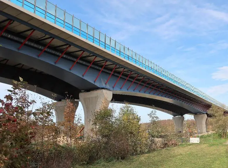
Curved soffits require internal transverse flange stiffeners to resist the radial component of force, though this is not onerous with large radii. Curvature is usually applied only to the major span and to the spans on either side of it.
With trapezoidal sections, a variation in depth will result in either a change in the width of one of the flanges along the bridge, or the web inclination will change. The appearance of the latter is likely to be somewhat disquieting, unless unnoticeably minor, and the former is to be preferred. Indeed, when well executed the former arrangement can produce a particularly good appearance.
Initial selection of flange and web sizes
The flange and web sizes depend on the configuration of the cross-section and the bending/torsional moments to be carried. A first estimate of sizes can be based on simple approximations and quickly refined to a better initial selection suitable for use in the detailed design.
The first rough estimate is used to determine properties for a simple grillage model, which is used to give a better indication of the distribution of bending moments so that a better initial design can be made. Several iteration cycles are likely to be needed at this stage.
The girders will be made up of several sections, in lengths suitable for transportation. This gives scope for variation of make-up between the different sections. At the initial design stage, splice positions should be considered and advantage taken to change plate thicknesses where appropriate. The main girders should normally be structural steel to grade S355 of BS EN 10025 since it is more cost-effective than lower grades.
Typical Construction Considerations of Composite Box Girder Bridges
The preliminary design of composite box girders should take into account their construction, performance, and maintenance. A composite box girder is not just a pair of plate girders with a common bottom flange. If proper account is not taken during the initial stage, the design will be less efficient and is likely to give rise to problems later which will be difficult to overcome.
Construction methodology: The designer should understand how the composite box girder is constructed. The flanges and webs will be fitted with stiffeners before they are assembled. Cross-frames or diaphragms will be needed at this stage to ensure that the cross-section is held in shape during welding. Closed trapezoidal boxes are usually assembled in an inverted position and the bottom flange is added last of all.
Internal Welding: Internal welding after closure is usually necessary; support diaphragms at least must be welded all around. Access and ventilation are more easily arranged in the shop than on site but even so, the amount of internal welding should be minimized where possible. It is difficult to ensure perfect alignment of every web and flange transverse stiffener at the corners and a connection detail, such as lapping, which will accommodate small differences should be chosen.
Type of welding: Joints between flanges and webs are easier and cheaper to make as fillet welds, rather than as butt welds. Butt welds are used in box girders for railway loading, where fatigue is more onerous; they are not necessary for highway bridges.
Transportation: After assembly, the box will have to be transported. In the UK, there are limits on length (27.4 m long) and width (4.3 m wide) for unrestricted travel on public roads, but larger sizes can be carried by special permission. Advice should be sought from the appropriate highway authority for travel in the relevant localities.
Stiffeners: Fitting and welding of stiffeners is expensive, and it is often cheaper to use thicker plate with less stiffening. Butt welds allow a change of plate thickness where stresses are lower, but making the weld may be more expensive than using the thicker plate throughout an individual length of girder.
Splices: Bolted splices are quicker to make on site, but sealing details at the ends of cover plates must be considered. If welding is used for the web and flange splices, bolting can still be effective internally for splicing longitudinal stiffeners. Such stiffeners should always be spliced with cover plates because true alignment is very difficult to achieve.
Support Bearing: Articulation arrangements (the configuration of fixed, guided, and free bearings) should be established at an early stage so that bearing positions, bearing stiffener requirements, and the need for bracing between boxes at supports can be determined.
Internal Drainage: It is important to consider drainage internally and avoid closed corners where moisture and dirt can collect. Composite box girders in this span range are often compared with prestressed concrete box girders. In such a comparison, the advantages of the steel girder in speed and ease of construction on site should be fully recognized.
Corrosion Protection and Inspection: Externally, the surface of the steel girder is durable, using modern protection systems or weather-resistant steel. Internally, the environment is closed and should require no more than routine inspection.
Contractor’s Experience: Advice on fabrication details and construction schemes should be sought from an experienced fabricator during the design stage, though it must be recognized that individual fabricators have particular preferences arising from their experience and workshop facilities.

