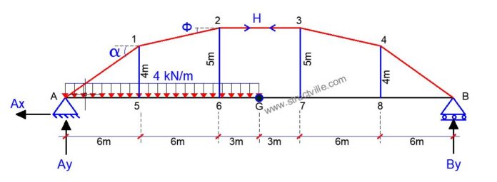
For the given arch bridge loaded, as shown above, determine the following;
(a) The support reactions
(b) The bending moment diagram of the girder
(c) The shear force diagram of the girder
(d) The axial force diagram of the girder
Support Reactions
∑MB = 0
30Ay – (4 × 15) × (15/2 + 15) = 0
30Ay – 1350 = 0
Therefore; Ay = 1350/30 = 45 kN
∑MGL= 0
15Ay – (4 × 152)/2 + 5H = 0
15(45) + 5H = 0
Therefore; H = -225/5 = -45 kN
∑MA = 0
30By – (4 × 152)/2 = 0
30By – 450 = 0
Therefore; By = 450/30 = 15 kN
∑MGR= 0
15By + 5H = 0
15(15) + 5H = 0
Therefore; H = -225/5 = -45 kN
Analysis of the Joints
Joint 2

φ = tan-1(1/6) = 9.46°
∑FX = 0
-F2-1cosφ + H = 0
-F2-1cos9.46 – 45 = 0
-F2-1 = 45/cos 9.46 = 45.62 kN
F2-1 = -45.62 kN
∑FY = 0
-F2-1sinφ – F2-6 = 0
-F2-6 = F2-1sinφ
-F2-6 = -45.62 sin9.46 = 7.498 kN
F2-6 = 7.498 kN
Joint 1

α = tan-1(4/6) = 33.69°
∑FX = 0
-F1-Acosα + F1-2sinφ = 0
-F1-Acosα – 45.62sin(9.46) = 0
-F1-A = 45.62sin(9.46)/cos(33.69) = 54.082 kN
F1-A = -54.082 kN
∑Fy = 0
-F1-Asinα + F1-2sinφ – F1-5 = 0
54.082sin(33.69) – 45.62sin9.46 – F1-5 = 0
22.501 – F1-5 = 0
F1-5 = 22.501 kN
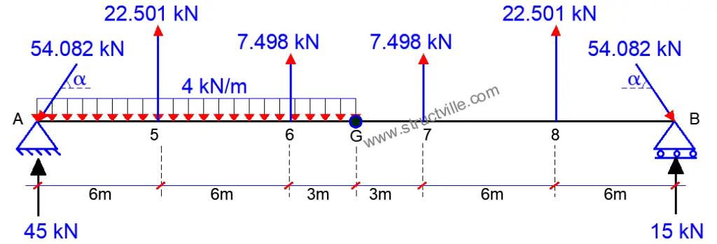
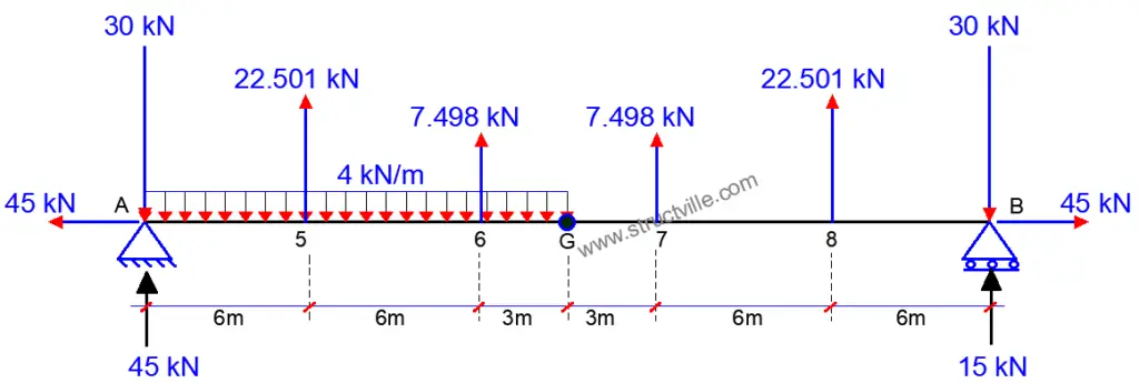
Therefore, the loading on the girder can be summarised as follows;

When the inclined forces are resolved into their vertical and horizontal components;
Fy = 54.082sinα = 54.082sin(33.69) = 30 kN
Fx = 54.082cosα = 54.082cos(33.69) = 45 kN

Check;
∑Fy ↑ = 45 + 15 + 2(22.501)+ 2(7.498) = 120 kN
∑Fy ↓ = (4 × 15) + 2(30) = 120 kN
Bending Moment
(Coming from the left)
MA = 0
M5 = (45 × 6) – (30 × 6) – (4 × 62)/2 = 18 kNm
M6 = (45 × 12) – (30 × 12) – (4 × 122)/2 + (22.501 × 6) = 27 kNm
MGL = (45 × 15) – (30 × 15) – (4 × 152)/2 + (22.501 × 9) + (7.498 × 3) = 0
(Coming from the right)
MB = 0
M8 = (15 × 6) – (30 × 6) = -90 kNm
M7 = (15 × 12) – (30 × 12) + (22.501 × 6) = -45 kNm
MGR = (15 × 15) – (30 × 15) + (22.501 × 9) + (7.498 × 3) = 0

Shear Force
VA = 45 – 30 = 15 kN
V5L = 45 – 30 – (4 × 6) = -9 kN
V5R = 45 – 30 – (4 × 6) + 22.501 = 13.501 kN
V6L = 45 – 30 – (4 × 12) + 22.501 = -10.499 kN
V6R = 45 – 30 – (4 × 12) + 22.501 + 7.498 = -3 kN
VG = 45 – 30 – (4 × 15) + 22.501 + 7.498 = -15 kN
V7L = -15 kN
V7R = -15 + 7.498 = -7.502 kN
V8L = -7.502 kN
V8R = -7.502 + 22.510 = 15 kN
VB = 15 kN

Axial Force
NA-B = H = Ax = 45 kN (Tension)


