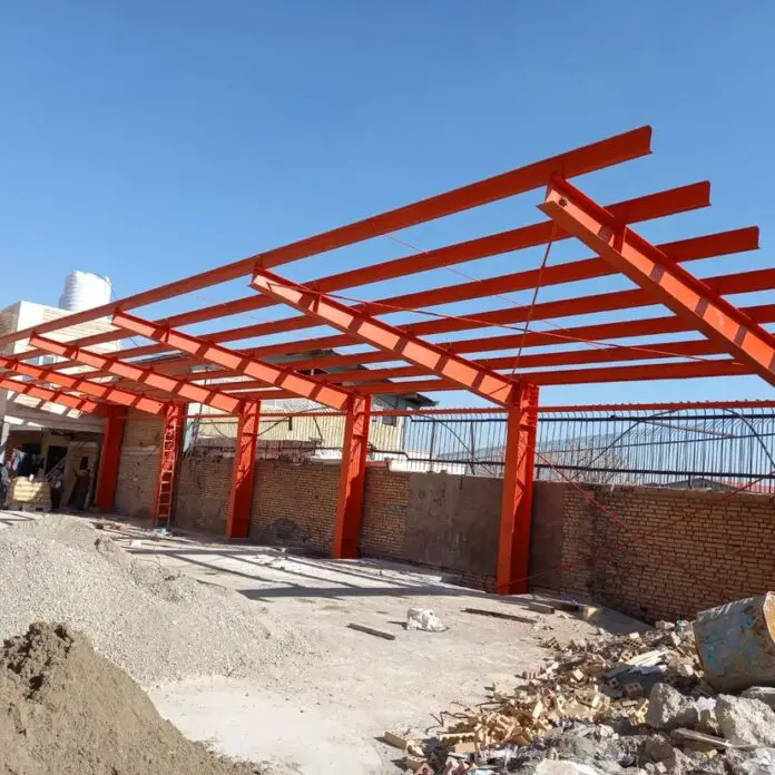
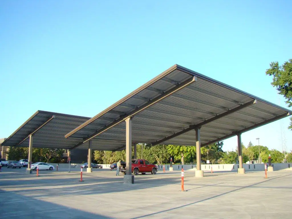
Cantilever steel carports have become increasingly popular due to their clean aesthetics, simplicity, minimal space requirements, and ability to span large distances without obstructing parking space. However, the unique structural demands of this design system necessitate careful consideration during the design process. The design of cantilever steel carports is consistent with the design of an open monopitch canopy roof according to EN 1991-1-4.
The design of steel carports involves the selection of adequate steel columns and beams that will be able to withstand the dead, live, and environmental loads that the structure will be subjected to without undergoing excessive deflection, vibration, or failure.
This article discusses the structural design for cantilever steel carports, exploring key principles, considerations, and design approaches.
Structural System of Cantilever Carports
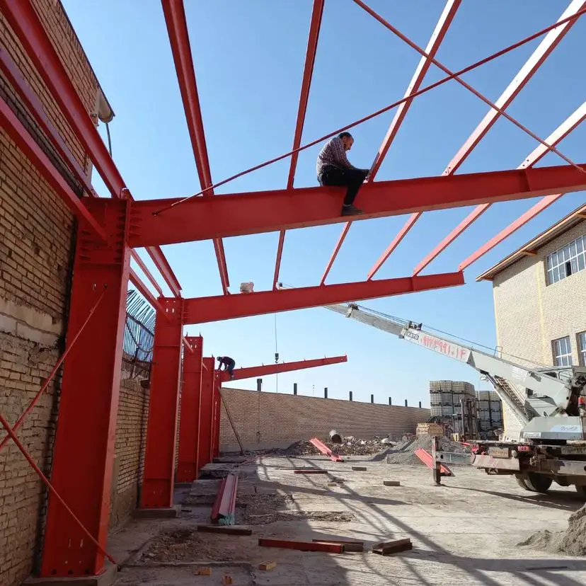
Cantilever steel beams are structural systems that project outwards like outstretched arms. Technically, most steel carport frame structures fall under monopitch canopy roof systems for their wind load analysis and design. This structural system offers elegance, efficiency, and expansive coverage, finding diverse applications in bridges, balconies, and yes, even carports. But beneath their deceptively simple appearance lies a complex interplay of forces, internal stresses, and deformations.
Cantilever beams project outward from support columns without additional support at the free end. This creates a significant bending moment force at the fixed end, necessitating robust column and foundation design.
Bending Moment
Imagine a cantilever beam of a carport structure bearing a load at its free end. The beam tries to resist this bending, leading to the development of internal stresses. The top fibres experience tension, stretching as the beam deflects downwards. Conversely, the bottom fibres are compressed, pushing inwards. This stress distribution is not uniform but varies parabolically across the beam’s depth, with the maximum values occurring at the top and bottom surfaces.
Shear force
While bending usually governs overall behaviour of carport frames, shear forces also play a critical role. Imagine slicing the beam at any section. The internal forces acting across this imaginary cut represent the shear force, responsible for balancing the applied load. This force varies along the beam length, reaching a maximum value at the support and decreasing towards the free end. Understanding shear distribution is critical for selecting appropriate beam sections and preventing shear failure.
Deflection
As the beam of a carport frame bends, the free end undergoes deflection, a measure of its vertical displacement. While deflection is inevitable, excessive movement can be detrimental. Factors like beam length, material properties, load magnitude, and support conditions all influence deflection. Engineers utilize engineering mechanics principles and advanced beam theory to calculate deflections and ensure they stay within acceptable limits.
Buckling
While bending and shear are often the primary concerns, slender beams face an additional problem – buckling. Imagine pushing a long, thin ruler sideways; it bends easily. Likewise, slender beams under compression can buckle, losing their load-carrying capacity abruptly. Engineers carefully assess the risk of buckling based on beam geometry, material properties, and loading conditions, employing design techniques like increasing section depth or adding lateral supports to mitigate the risk.
Connection Details
The design doesn’t end with the beam and column structures of the carport. The connections between the structural elements play a vital role in overall behaviour. Welded, bolted, or a combination of connections transfer internal forces between the beam and the support. Improperly designed or executed connections can lead to premature failure, highlighting the importance of careful design, fabrication, and quality control during construction.
Load Analysis
Several loads and load combinations must be accounted for in the design of carports and they typically include:
Dead Loads: Weight of the steel structure, roof covering, and any attachments such as solar panels, electrical/mechanical services, and insulations (though rarely included).
Live Loads: Human access due to erection or maintenance, snow accumulation, and wind pressures. Wind pressure appears to be the most critical load in the design of carport structural systems.
Seismic Loads: Relevant in seismically active regions.
Load Path and Equilibrium: The design ensures a clear and efficient load path from the roof to the columns, foundation, and ultimately the soil. Counterbalancing is often required to achieve equilibrium, achieved through structural elements or anchor design.
Structural Analysis
For complex structural configurations or demanding loading scenarios, advanced analysis techniques like Finite Element Analysis (FEA) become invaluable. FEA software creates a digital model of the structure, discretizing it into smaller elements and applying loads. By solving complex mathematical equations, the software calculates stresses, deflections, and buckling potential at various points within the beam, providing valuable insights beyond analytical solutions.
Structural Design of Carport Structures
Each structural member in the carport frame is individually designed to resist the anticipated loads. This involves:
Beam Design: Selecting appropriate beam sections (e.g., universal beam sections) and checking for bending stress, shear stress, and deflection within allowable limits as per design codes.
Column Design: Designing columns to resist axial loads, bending moments, and potential buckling. Steel column design tables or specific software tools can be employed.
Connection Design: Designing connections between members to ensure adequate strength and stiffness. Welded, bolted, or a combination of connections are used, following code-specified design procedures.
Member Design Example
It is desired to design a monopitch canopy steel carport structure with the details provided below;

Structure data
Height of column = 2.5m
Length of beam = 3.027m
Spacing of frame members = 3.0 m c/c
Spacing of purlins = 0.605m
Angle of inclination of roof = 7.59 degrees
Dead Load
Unit weight of sheeting material = 0.02 kN/m2
Self-weight of members (calculated automatically)
Services (assume) = 0.1 kN/m2
Live Load
Imposed live load = 0.6 kN/m2
Wind Load Analysis of carport Monopitch Canopy Structures
Wind speed = 40 m/s
Basic wind velocity (Exp. 4.1); v = cdir × cseason × vb,0 × cprob = 40.8 m/s
Degree of blockage under the canopy roof: φ = 0
Reference mean velocity pressure; qb = 0.5 × ρ × vb2 = 1.020 kN/m2
Reference height (at which q is sought); z = 2900 mm
Displacement height (sheltering effects excluded); hdis = 0 mm
Aref = bd / cos(α) = 9.000 m ⋅ 3.000 m / 0.991 = 27.239 m2

Mean wind velocity
The mean wind velocity vm(ze) at reference height ze depends on the terrain roughness, terrain orography and the basic wind velocity vb. It is determined using EN1991-1-4 equation (4.3):
vm(ze) = cr(ze) ⋅ c0(ze) ⋅ vb = 0.7715 × 1.000 × 40.00 m/s = 30.86 m/s
Wind turbulence
The turbulence intensity Iv(ze) at reference height ze is defined as the standard deviation of the turbulence divided by the mean wind velocity. It is calculated in accordance with EN1991-1-4 equation 4.7. For the examined case ze ≥ zmin.
Iv(ze) = kI / [ c0(ze) ⋅ ln(max{ze, zmin} / z0) ] = 1.000 / [ 1.000 ⋅ ln(max{2.900 m, 2.0 m} / 0.050 m) ] = 0.2463
Basic velocity pressure
The basic velocity pressure qb is the pressure corresponding to the wind momentum determined at the basic wind velocity vb. The basic velocity pressure is calculated according to the fundamental relation specified in EN1991-14 §4.5(1):
qb = (1/2) ⋅ ρ ⋅ vb2 = (1/2) ⋅ 1.25 kg/m3 ⋅ (40.00 m/s)2 = 1000 N/m2 = 1.000 kN/m2
where ρ is the density of the air in accordance with EN1991-1-4 §4.5(1). In this calculation the following value is considered: ρ = 1.25 kg/m3. Note that by definition 1 N = 1 kg⋅m/s2.
Peak velocity pressure
The peak velocity pressure qp(ze) at reference height ze includes mean and short-term velocity fluctuations. It is determined according to EN1991-1-4 equation 4.8:
qp(ze) = (1 + 7⋅Iv(ze)) ⋅ (1/2) ⋅ ρ ⋅ vm(ze)2 = (1 + 7⋅0.2463) ⋅ (1/2) ⋅ 1.25 kg/m3 ⋅ (30.86 m/s)2 = 1621 N/m2
⇒ qp(ze) = 1.621 kN/m2
Calculation of local wind pressure on the canopy roof
Net pressure coefficients
The net pressure coefficients cp,net represent the maximum local pressure for all wind directions and they should be used in the design of local elements such as roofing elements and fixings. Net pressure coefficients are given for three zones A, B, C as defined in the figure included in EN1991-1-4 Table 7.6 that is reproduced above. Zones B, C extend at the sides of the canopy and Zone A at the central region:
The inclined length of the monopitch canopy roof parallel to the wind direction is:
d’ = d / cos(α) = 3.000 m / 0.991 = 3.027 m
Zone C corresponds to the regions parallel to the windward and leeward edges having width d’/10 = 0.303 m. Zone B corresponds to the regions parallel to the side edges having width b/10 = 0.900 m, where b is the width of the canopy transverse to the wind direction. Zone A corresponds to the remaining central region.
The net pressure coefficient cp,net for each of the zones A, B, C are defined in EN1991-1-4 Table 7.6 as a function of the roof angle α and the blockage factor φ. For the examined case: α = 7.59 ° and φ = 0.000. Therefore according to EN1991-1-4 Table 7.6 the following net pressure coefficients and overall force coefficient are obtained, using linear interpolation where appropriate:
For zone A: cp,net,A = -1.307 or +1.007
For zone B: cp,net,B = -1.855 or +2.255
For zone C: cp,net,C = -1.955 or +1.455
Negative values for the external pressure coefficient correspond to suction directed away from the upper surface inducing uplift forces on the roof. Both positive and negative values should be considered for each zone.
Net wind pressure on pressure zones
The net wind pressure on the surfaces of the structure wnet corresponds to the combined effects of external wind pressure and internal wind pressure. For structural surfaces consisting of only one skin the net pressure effect is determined as:
wnet = cp,net ⋅ qp(ze)
For structural surfaces consisting of more than one skin EN1991-1-4 §7.2.10 is applicable. For the different pressure zones on the canopy roof the following net pressures are obtained:
– For zone A: wnet,A = -2.119 kN/m2 or +1.633 kN/m2
(zones A is the remaining central region located more than d’/10 = 0.303 m or b/10 = 0.900 m from the edges)
– For zone B: wnet,B = -3.008 kN/m2 or +3.657 kN/m2
(zone B extends up to b/10 = 0.900 m from the side edges)
– For zone C: wnet,C = -3.170 kN/m2 or +2.360 kN/m2
(zone C extends up to d’/10 = 0.303 m from the windward and leeward edges)
Negative net pressure values correspond to suction directed away from the external surface inducing uplift forces on the canopy roof. Both positive and negative values should be considered.
Calculation of overall wind force on the canopy roof
Overall pressure coefficient
The overall pressure coefficient cf represents the overall wind force and it should be used in the design of the overall load bearing structure. The overall pressure coefficient cf is defined in EN1991-1-4 Table 7.6 as a function of the roof angle α and the blockage factor φ. For the examined case: α = 7.59 ° and φ = 0.000. Therefore according to EN1991-1-4 Table 7.6 the following overall pressure coefficient is obtained, using linear interpolation where appropriate:
cf = -0.804 or 0.452
Negative values for the overall pressure coefficient correspond to suction directed away from the upper surface inducing uplift forces on the roof. Both positive and negative values should be considered.
Structural factor
The structural factor cscd takes into account the structure size effects from the non-simultaneous occurrence of peak wind pressures on the surface and the dynamic effects of structural vibrations due to turbulence. The structural factor cscd is determined in accordance with EN1991-1-4 Section 6. A value of cscd = 1.0 is generally conservative for small structures not-susceptible to wind turbulence effects such as buildings with heights less than 15 m.
In the following calculations, the structural factor is considered as cscd = 1.000.
Overall wind force (for total roof surface)
The wind force Fw corresponding to the overall wind effect on the canopy roof is calculated in accordance with EN1991-1-4 equation 5.3:
Fw = cscd ⋅ cf ⋅ Aref ⋅ qp(ze)
where Aref = 27.239 m2 is the reference wind area of the canopy roof as calculated above.
For the examined case:
– Maximum overall wind force (acting downwards):
Fw = 1.000 ⋅ (+0.452) ⋅ 27.239 m2 ⋅ 1.621 kN/m2 = +19.95 kN
– Minimum overall wind force (acting upwards):
Fw = 1.000 ⋅ (-0.804) ⋅ 27.239 m2 ⋅ 1.621 kN/m2 = -35.49 kN
Negative values correspond to suction directed away from the external surface inducing uplift forces on the canopy roof. Both positive and negative values should be considered, as explained below.
Direction and eccentricity of the overall wind force
According to EN1991-1-4 §7.3(6) and the National Annex the location of the centre of pressure is defined at an eccentricity e from the windward edge. In this calculation, the centre of pressure is considered at an eccentricity e = 0.250⋅d’ = 0.757 m, where d’ = 3.027 m is the inclined length of the canopy roof parallel to the wind direction. Two cases should be examined for the overall effect of the wind force on the canopy roof:
- Maximum force Fw = +19.95 kN (i.e. acting downwards) located at a distance e = 0.757 m from the windward edge.
- Minimum force Fw = -35.49 kN (i.e. acting upwards) located at a distance e = 0.757 m from the windward edge.
Structural Analysis and Results
Finite Element Analysis (FEA) software (Staad Pro) was used to model the structure and evaluate stresses, deflections, and buckling potential under various load combinations.
Structural Modelling and Loading
Some of the images from the structural model are shown below.


Support Reactions
The support reactions from the various load combinations are shown below.


The summary of the maximum and minimum support reactions under various load combinations are shown in the Table below.

Bending Moment and shear force diagrams
The typical bending moment and shear force diagrams from the various load combinations are shown below.


Design of the Cantilever Beams
The summary of the maximum stresses occurring on the beams is shown below. An abridged design calculations are presented afterwards.

Section type; UB 254x146x37 (BS4-1)
Steel grade – EN 10025-2:2004; S275
Nominal thickness of element; tnom = max(tf, tw) = 10.9 mm
Nominal yield strength; fy = 275 N/mm2
Nominal ultimate tensile strength; fu = 410 N/mm2
Modulus of elasticity; E = 210000 N/mm2

The section is Class 1
Check shear
Height of web; hw = h – 2tf = 234.2 mm; h = 1.000
hw / tw = 37.2 = 40.2ε/ h < 72ε / h
Shear buckling resistance can be ignored
Design shear force; Vy,Ed = 32.8 kN
Shear area – cl 6.2.6(3); Av = max(A – 2btf + (tw + 2r)tf, hhwtw) = 1759 mm2
Design shear resistance – cl 6.2.6(2); Vc,y,Rd = Vpl,y,Rd = Av × (fy / √(3)) / γM0 = 279.3 kN
Vy,Ed / Vc,y,Rd = 0.118
Check bending moment
Design bending moment; My,Ed = 61.7 kNm
Design bending resistance moment – eq 6.13; Mc,y,Rd = Mpl,y,Rd = Wpl.y fy / γM0 = 132.9 kNm
My,Ed / Mc,y,Rd = 0.464
Slenderness ratio for lateral torsional buckling
Correction factor – For cantilever beams; kc = 1
C1 = 1 / kc2 = 1
Poissons ratio; n = 0.3
Shear modulus; G = E / [2(1 + n)] = 80769 N/mm2
Unrestrained effective length; L = 1.0Lz_s1 = 3000 mm
Elastic critical buckling moment; Mcr = C1π2EIz / L2 × √(Iw / Iz + L2GIt / (π2EIz)) = 205.5 kNm
Slenderness ratio for lateral torsional buckling; λLT = √(Wpl.yfy / Mcr) = 0.804
Limiting slenderness ratio; λLT,0 = 0.4
λLT > λLT,0 – Lateral torsional buckling cannot be ignored
Check buckling resistance
Buckling curve – Table 6.5; b
Imperfection factor – Table 6.3; αLT = 0.34
Correction factor for rolled sections; β = 0.75
LTB reduction determination factor; φLT = 0.5[1 + αLT(λLT – λLT,0) + βλLT2] = 0.811
LTB reduction factor – eq 6.57; cLT = min(1 / [φLT + √(φLT2 – βλLT2)], 1, 1 /λLT2) = 0.815
Modification factor; f = min(1 – 0.5(1 – kc) × [1 – 2(λLT – 0.8)2], 1) = 1.000
Modified LTB reduction factor – eq 6.58; cLT,mod = min(cLT /f, 1, 1 / λLT2) = 0.815
Design buckling resistance moment – eq 6.55; Mb,y,Rd = cLT,modWpl.yfy / γM1 = 108.3 kNm
My,Ed / Mb,y,Rd = 0.57
Check for Deflection
The following deflection values were obtained for the structure;
Unfactored dead load = 5.423 mm
Unfactored live load = 9.507 mm
Positive wind load (downwards) = 38.4 mm
Negative wind load (upwards) = 40.827 mm
With this information, an appropriate deflection limit can be adopted for the structure.
Design of the columns
The summary of the maximum stresses occurring on the columns is shown below. An abridged design calculations are presented afterwards.


Combined bending and axial compression (cl. 6.3.3)
Characteristic resistance to normal force; NRk = Afy = 1150 kN
Characteristic moment resistance – Major axis; My,Rk = (Wpl.yfy) = 132.2 kNm
Characteristic moment resistance – Minor axis; Mz,Rk = Wpl.z fy = 16.5 kNm
Moment factor – Major axis; Cmy = 0.9
Moment factor – Minor axis; Cmz = 0.9
Moment distribution factor for LTB; ψLT = My,Ed2 / My,Ed1 = 0.842
Moment factor for LTB; CmLT = max(0.4, 0.6 + 0.4 ´ yLT) = 0.937
Interaction factor kyy;
kyy = Cmy [1 + min(0.8, λy – 0.2) NEd / (χyNRk / γM1)] = 0.901
Interaction factor kzy;
kzy = 1 – min(0.1, 0.1λz)NEd / ((CmLT – 0.25)(χzNRk/γM1)) = 0.985
Interaction factor kzz;
kzz = Cmz [1 + min(1.4, 2λz – 0.6)NEd / (czNRk / γM1)] = 1.029
Interaction factor kyz;
kyz = 0.6kzz = 0.617
Section utilisation;
URB_1 = NEd / (χyNRk / γM1) + kyyMy,Ed / (cLTMy,Rk / γM1) + kyzMz,Ed / (Mz,Rk / γM1)
URB_1 = 0.690
URB_2 = NEd / (χzNRk / γM1) + kzyMy,Ed / (cLTMy,Rk / γM1) + kzzMz,Ed / (Mz,Rk / γM1)
URB_2 = 0.810
Design of the Foundation
Understanding soil properties is critical for foundation design. Geotechnical investigations determine soil-bearing capacity and potential for settlement. The design of the foundation should pay good attention to uplift, sliding and overturning moment from the wind load.
Depending on soil conditions and design loads, foundations can be:
Spread Footings: Individual concrete pads for each column.
Continuous Footings: A continuous concrete strip supporting multiple columns.
Mat Foundation: A concrete slab supporting the entire structure.
Anchor Design: Anchors embedded in the foundation resist uplift forces generated by wind and seismic loads. Anchor selection and embedment depth are critical for structural stability.
Fabrication and Construction Considerations
- Shop Drawings and Fabrication: Detailed shop drawings ensure accurate fabrication of steel components. Quality control during fabrication is paramount.
- Erection and Field Welding: Proper erection procedures and qualified welders are necessary to ensure structural integrity and safety.
- Inspection and Quality Control: On-site inspections at various stages of construction verify adherence to design specifications and ensure construction quality.
Conclusion
Cantilever steel carports offer an aesthetically pleasing and practical solution for vehicle protection. However, due to their inherent structural challenges, their design requires meticulous attention to detail. A clear understanding of the load paths, material properties, design codes, and analysis methods is essential for a safe and reliable structure. Consulting with qualified structural engineers throughout the design and construction process is crucial to ensure a successful and long-lasting cantilever steel carport.

