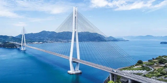
In cable-stayed bridges, the main purpose of the pylon is to transfer the forces resulting from anchoring the cable stays to the foundation. As a result, these forces will significantly influence the design of the pylon. The tensile cable forces in cable-stayed bridges are part of a closed force system that balances these forces with the compression that occurred within the deck and the pylon. Ideally, the pylon should resist these forces through axial compression whenever feasible to minimize any uneven loading.
The pylon serves as the central element that defines the visual appearance of a cable-stayed bridge, offering a chance to impart a unique style to the overall design. Additionally, the pylon’s design must be adaptable to different stay cable layouts, accommodate the bridge site’s topography and geology, and support the forces efficiently and cost-effectively. The stability of cable-stayed bridges is dependent on the stability and stiffness of the pylons.
Pylons for cable-stayed bridges are predominantly constructed using structural steel, reinforced concrete, or composite sections.
Steel Pylons
Early designs of cable-stayed bridge pylons mostly involved steel boxes, like the Stromsmund Bridge (opened in 1956). The pylons resembled steel portal frames meant to offer transverse restraint to the stay system. However, it was subsequently observed that this restraint was unnecessary as the stay system itself could provide sufficient transverse restraint.
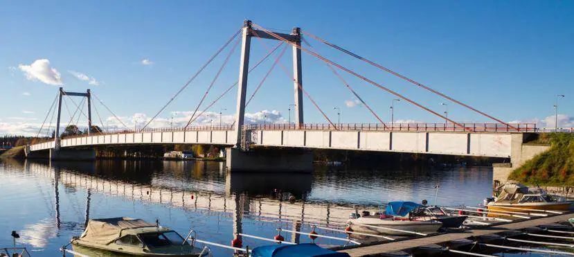
When a single mast supports each stay plane, any lateral displacement at the top of the mast results in a rotation of the stay plane. This rotation ensures that the resultant reaction from the main span and back span stay cables passes through the foot of the pylon. The weight of the pylon remains vertical, but the reaction from the stays dominates. Thus, the effective length of the mast in buckling is not twice the height (2H) of a simple cantilever, but equal to the height (H).
In the longitudinal direction, the main and back stay cables restrain the pylon against buckling as long as the deck, to which the stays are anchored, is properly restrained against longitudinal movement. If the deck is unrestrained, the pylon will behave as a cantilever with maximum bending at the base, resulting in an effective length of twice the height (2H) in buckling.

Effective pylon restraint can be achieved when the deck is adequately connected to an abutment, another pylon, or an independent gravity anchorage. Earlier designs used a pin at the pylon foot to prevent large bending moments on the mast. Modern designs prefer a fixed-end cantilever mast, which is simpler and more stable during erection. The use of a frictionless bearing with a fixed-end mast is possible when the member is slender enough, causing the axial load to approach the buckling capacity of the mast in a free cantilever condition.
For single mast pylons supporting a single plane of stays, two methods have been used to connect the mast at its base:
(1) encastre construction into a transverse girder forming part of the deck, requiring bearings at the pylon foundation, and
(2) passing the mast directly through the deck to sit upon the pylon foundation, needing bearings only at each end of the transverse girder.
The second method (Method 2) is more efficient and has been widely adopted in recent designs.
Concrete Pylons
Concrete has become increasingly competitive for pylon construction due to advancements in concrete construction and formwork technology, despite its higher self-weight compared to steel. Concrete has proven to be particularly adaptable to complex pylon forms.
Various types of pylons have been developed to support both vertical and inclined stay layouts, including H-frame, A-frame, and inverted Y-frame pylons (shown in Figure 3).

In the case of H-frame pylons, the stay anchors are usually located above a crossbeam. For modified fan arrangements of stays, this crossbeam would be positioned between mid-height and two-thirds of the pylon height above the deck. However, when adopting the harp arrangement of stays, the anchors are distributed over the full height of the pylon above the deck. In such cases, a crossbeam can only be practically provided below the deck level, as seen in the Øresund Bridge between Denmark and Sweden.
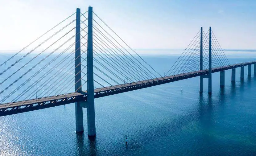
The deck section located at the pylon is typically subjected to the highest stresses, combining maximum negative moment and axial load. Connecting the stay directly between the pylon leg and an edge stiffening girder within the deck requires the pylon legs to be inset into the deck.
This creates a practical detailing problem and results in a zone of concentrated stress in an already highly stressed section. Several geometrical configurations can overcome this problem: widening the pylon and connecting the stays to the deck using out-stand brackets, or sloping the pylon leg outwards at its base.
The pylon leg can be inclined over its entire height, in which case the pylon must be designed to accommodate a small eccentricity arising from the stay cable reactions. Another approach is to maintain the upper section of the leg in a vertical plane and incline the pylon only from below the level of the bottom anchorage.
By locating the crossbeam at this change of direction, the stay force reaction can be efficiently transmitted as a direct thrust. Examples of this pylon geometry can be observed in the Annacis Bridge over the Fraser River, Canada (see Figure 5), and the Vasco da Gama Bridge (Capra and Leveille, 1998) over the Tagus River, Portugal.
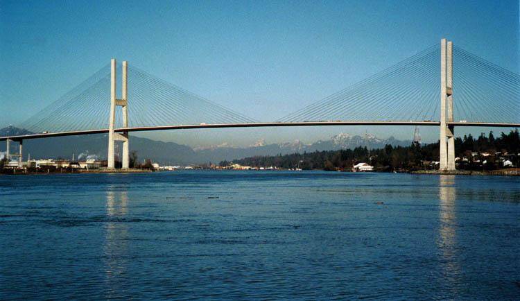
Pylon Geometry
The A-frame pylon is well-suited for inclined stay arrangements and was first used in the Severins Bridge. Another variation is the inverted Y-frame, where the vertical leg, containing the stay anchors, extends above the bifurcation point. Examples of the inverted Y-frame can be seen in the Normandy Bridge over the River Seine, France, and the Rama VIII Bridge in Bangkok, Thailand.
However, the wide footprint of the inverted Y-frame can lead to excessive land usage when a high navigation clearance to the deck is necessary. To address this, some designs break the pylon legs at or just below the deck, creating inward-leaning legs to the foundation, forming a diamond configuration (Figure 6).

This modification reduces land usage but makes the pylon less stiff against transverse wind or seismic forces, resulting in increased deflection. To counteract this deflection, a substantial increase in stiffness is required in the lower section of the pylon leg below the deck.
Nevertheless, this diamond configuration was favoured for the pylons of the Tatara Bridge in Japan, currently the world’s longest cable-stayed span at 890m, and the Industrial Ring Road Bridges in Bangkok. The same configuration was also used for the twin cable-stayed crossing of the Houston Ship Channel, where the twin diamonds were connected and tied together at the deck level to form a strong truss, transmitting transverse wind loads to the foundations.

Another architectural feature includes inclining the pylon in the longitudinal direction, resulting in visually exciting structures. However, this design introduces inclined thrust from the pylon that must be carried by the foundation, generating a significant horizontal component. In rock foundations, these horizontal reactions are easily resisted with only minor foundation displacement. In contrast, in typical estuarine soil conditions, foundation costs may represent a significant portion of the overall project cost.
Cable Stay Connection to the Pylons
In early designs, the connection between the stays and the pylon resembled that of suspension bridges, where the cables were laid in a deviator saddle and carried through the pylon. However, this method had limitations. As an alternative, modified fan and harp arrangements were introduced, with stays anchored over the upper section of the pylon leg. This led to the use of separate stays for the main span and back span.
The most straightforward anchoring method involves attaching the stay socket or anchorage plate directly to the pylon wall. In concrete pylons, the horizontal component of the cable forces can cause the shaft to split vertically, requiring transverse pre-stressing to resist these forces. Different layouts were developed to address this, as seen in Figures 8 and 9.


To simplify pylon construction and ensure accurate placement of steel formers, anchor pre-stress, and reinforcement within the concrete walls, steel fabricated anchorage modules have been utilized. These modules define the required stay anchorage geometry and are incorporated into the concrete shaft during construction.
Adequate shear connection, typically in the form of shear studs, allows the anchorage forces in the fabrication to be transferred to the concrete shaft. Examples of this construction method, with the fabricated anchorage module centrally located within the concrete shaft, can be seen in the Normandy Bridge and the Stonecutters Bridge. The Ting Kau Bridge in Hong Kong also used a similar concept but connected the fabricated anchor modules on the outside of the concrete core.
It is very important to accurately model any eccentricity of the stay anchor within the pylon during structural analysis. The inclination of the back span stays and main span stays are usually different, requiring the anchors to be located at different levels to maintain the same intersection line on the pylon centerline.
Alternatively, keeping the levels of the two anchors the same may slightly eccentrically place the vertical resultant of the stay forces to the pylon. This approach simplifies the anchor zone detailing but requires careful consideration of the pylon moments arising from this small eccentricity (Figure 10).

Conclusion
In conclusion, pylons play a crucial role in the structural integrity and aesthetic appeal of cable-stayed bridges. The use of pylons in these bridges has evolved over time, with advancements in concrete construction and formwork technology making concrete pylons increasingly competitive, despite their higher self-weight compared to steel alternatives.
Various types of pylons have been developed to accommodate different stay arrangements, including H-frame, A-frame, and inverted Y-frame pylons. The modified fan and harp arrangements have allowed for separate stays for the main span and back span, enabling more adaptable and efficient designs.
Pylon geometry has been a subject of innovation and consideration in recent designs. Solutions such as breaking the pylon legs to create inward-leaning legs or using steel-fabricated anchorage modules have been employed to reduce land usage and simplify construction processes. However, these modifications must be carefully designed to maintain sufficient stiffness and resist transverse wind or seismic forces.
The design of pylons in cable-stayed bridges must take into account various factors, such as the inclination of the back span and main span stays, the connection between the stays and the pylon, and the accurate modelling of stay anchor eccentricities. These considerations are critical to ensuring the stability and performance of the cable-stayed bridge.
In summary, pylons in cable-stayed bridges continue to undergo refinement and innovation, striving to achieve optimal efficiency, safety, and aesthetics. The choice of pylon type, arrangement, geometry, and design are essential elements in the successful construction of cable-stayed bridges, contributing to their functionality, longevity, and architectural distinctiveness in modern infrastructure projects.
References:
Farquhar, D. J. (2008). Cable-stayed bridges. ICE Manual of Bridge Engineering. Published by the Institution of Civil Engineers (ICE) UK

