Cylindrical structures like tanks, silos, and chimneys are widely used in various industries, including oil and gas, agriculture, chemical processing, and water storage. These structures are susceptible to wind loads, which can cause significant stresses and potential failures if not properly analyzed and designed.
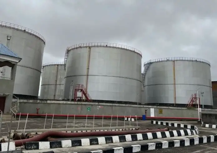
In industrial and agricultural settings, cylindrical above-ground vertical tank farms are commonly used for the storage of various liquids like petroleum, oil, water and fuel. These tanks are typically welded, thin-walled structures with large diameters, making them susceptible to buckling under wind loads when empty or partially filled.
The failure of such tanks can have devastating consequences, often resulting in significant financial and human losses. Additionally, these failures pose a serious threat to public safety and can have a detrimental impact on the environment.

This article discusses the wind load analysis for tank farms and other cylindrical structures, providing a comprehensive overview of the key factors, methodologies, and considerations for engineers.
Understanding Wind Loads
Wind loads are external forces acting on a structure due to the dynamic pressure and drag exerted by moving air. The magnitude and direction of wind loads depend on various factors, including:
- Basic Wind Speed (V): This is the reference wind speed, typically determined for a specific location and return period (e.g., 50-year return period). Building codes and standards like ASCE 7-16 (“Minimum Design Loads and Associated Systems for Buildings and Other Structures”) and EN 1991-1-4 provide wind speed maps for various regions.
- Exposure Category: This accounts for the surrounding terrain and influences the wind speed experienced by the structure. Different exposure categories are defined in codes, ranging from open terrain to urban and suburban environments.
- Topographic Effects: Local terrain features like hills and valleys can significantly influence wind speeds and turbulence intensity.
- Structure Shape and Size: The shape and size of the structure play a crucial role in determining the wind pressure distribution. Cylindrical structures experience wind loads differently compared to flat or rectangular structures.
Wind Load Analysis Methods for Cylindrical Structures
Several approaches can be adopted for wind load analysis of cylindrical structures:
- Simplified Methods: Building codes often provide simplified procedures for calculating wind pressures on basic shapes like cylinders. These methods typically involve applying an equivalent static wind pressure acting on the projected area of the structure. While convenient, these methods may not be suitable for complex geometries or situations with significant topographic effects.
- Analytical Methods: Analytical methods utilize established formulas based on wind tunnel experiments and theoretical principles to calculate wind pressures on cylindrical structures. These methods consider factors like wind speed, exposure category, and surface roughness. However, they may involve complex calculations and require specialized knowledge.
- Computational Fluid Dynamics (CFD): This advanced method employs computational software to simulate the flow of air around the structure. CFD can generate detailed pressure distributions on the entire structure, accounting for complex geometries and local effects. However, CFD analysis requires expertise and significant computational resources.

Specific Wind Load Considerations for Tank Farms
For the calculation of wind load action effects on circular cylinder elements, the total horizontal wind force is calculated from the force coefficient corresponding to the overall effect of the wind action on the cylindrical structure or cylindrical isolated element.
The calculated effective wind pressure weff and total wind force FW correspond to the total wind action effects and they are appropriate for global verifications of the structure according to the force coefficient method. For local verifications, such as verification of the cylinder’s shell, appropriate wind pressure on local surfaces must be estimated according to the relevant external pressure coefficients, as specified in EN1991-1-4 §7.9.1.
For cylinders near a plane surface with a distance ratio zg/b < 1.5 special advice is necessary. See EN1991-1-4 §7.9.2(6) for more details. For a set of cylinders arranged in a row with normalized center-to-center distance zg/b < 30 the wind force of each cylinder in the arrangement is larger than the force of the cylinder considered as isolated. See EN1991-1-4 §7.9.3 for more details.
The calculated wind action effects are characteristic values (unfactored). Appropriate load factors should be applied to the relevant design situation. For ULS verifications the partial load factor γQ = 1.50 is applicable for variable actions.
When analyzing wind loads on tank farms, additional factors come into play:
- Spacing and Interaction: The proximity of tanks within a farm can significantly influence wind pressures. Shielding effects and aerodynamic interaction between tanks need to be considered. Several empirical methods and CFD simulations are available to account for these effects.
- Appurtenances: Wind loads also act on appurtenances like piping, ladders, and platforms attached to tanks. These loads can be significant and need to be included in the overall wind load analysis.
- Dynamic Amplification: Tanks may experience dynamic amplification of wind loads due to their inherent dynamic properties. This can be particularly crucial for slender tanks or those with low natural frequencies.
Wind Load Analysis Example
A cylindrical structure of diameter (b) 5m and length (l) = 20 m is to be constructed in an area of terrain category II with a basic wind velocity vb of 40 m/s. The orientation of the cylindrical element is vertical and the maximum height above ground of the cylindrical element z = 20 m. The surface of the tank is made of galvanised steel. Calculate the wind force on the tank (Take Air density: ρ = 1.25 kg/m3)
Solution
Calculation of peak velocity pressure
The reference height for the wind action ze is equal to the maximum height above the ground of the section being considered, as specified in EN1991-1-4 §7.9.2(5). The reference area for the wind action Aref is the projected area of the cylinder, as specified in EN1991-1-4 §7.9.2(4). Therefore:
ze = z = 20 m
Aref = bl = 5 m × 20m = 100 m2
Basic wind velocity vb = 40 m/s.
For terrain category II the corresponding values are z0 = 0.050 m and zmin = 2.0 m.
The terrain factor kr depending on the roughness length z0 = 0.050 m is calculated in accordance with EN1991-1-4 equation (4.5):
kr = 0.19 ⋅ (z0 / z0,II)0.07 = 0.19 × (0.050 m / 0.050 m)0.07 = 0.19
The roughness factor cr(ze) at the reference height ze accounts for the variability of the mean wind velocity at the site.
cr(ze) = kr ⋅ ln(max{ze, zmin} / z0) = 0.19 × ln(max{20 m, 2 m} / 0.050 m) = 1.1384
The orography factor is considered as c0(ze) = 1.0
The mean wind velocity vm(ze)
vm(ze) = cr(ze) ⋅ c0(ze) ⋅ vb = 1.1384 × 1 × 40 m/s = 45.54 m/s
The turbulence intensity Iv(ze)
Iv(ze) = kI / [ c0(ze) ⋅ ln(max{ze, zmin} / z0) ] = 1.0 / [ 1.000 × ln(max{20 m, 2.0 m} / 0.050 m) ] = 0.1669
The basic velocity pressure qb
qb = (1/2)ρvb2 = (1/2) × 1.25 kg/m3× (40.00 m/s)2 = 1000 N/m2 = 1.000 kN/m2
where ρ is the density of the air in accordance with EN1991-1-4 §4.5(1). In this calculation, the following value is considered: ρ = 1.25 kg/m3.
The peak velocity pressure qp(ze) at reference height ze
qp(ze) = (1 + 7⋅Iv(ze)) ⋅ (1/2) ⋅ ρ ⋅ vm(ze)2 = (1 + 7 × 0.1669) × (1/2) × 1.25 kg/m3 × (45.54 m/s)2 = 2810 N/m2
⇒ qp(ze) = 2.810 kN/m2
The peak wind velocity v(ze) at reference height ze
v(ze) = [2 ⋅ qp(ze) / ρ ]0.5 = [2 × 2.810 kN/m2 / 1.25 kg/m3 ]0.5 = 67.05 m/s
Calculation of wind forces on the structure
The wind force on the structure Fw for the overall wind effect is estimated according to the force coefficient method as specified in EN1991-1-4 §5.3.
Fw = cscd ⋅ cf ⋅ qp(ze) ⋅ Aref
In the following calculations, the structural factor is considered as cscd = 1.000.
Reynolds number
Reynolds number characterizes the airflow around the object. For airflow around cylindrical objects, Reynolds number is calculated according to EN1991-1-4 §7.9.1(1):
Re = b ⋅ v(ze) / ν = (5 m × 67.05 m/s) / 15.0 × 10⁻⁶ m2/s = 22.3505 × 10⁶
where the kinematic viscosity of the air is considered as ν = 15.0 × 10⁻⁶ m2/s in accordance with EN1991-1-4 §7.9.1(1).
Effective slenderness
The effective slenderness λ depends on the aspect ratio and the position of the structure and it is given in EN1991-1-4 §7.13(2).
For circular cylinders with length l ≤ 15 m the effective slenderness λ is equal to:
λ15 = min(l / b, 70) = min(20m / 5m, 70) = 4
For circular cylinders with length l ≥ 50 m the effective slenderness λ is equal to:
λ50 = min(0.7l / b, 70) = min(0.7 × 20 m / 5 m, 70) = 2.800
For circular cylinders with intermediate length 15 m < l < 50 m the effective slenderness λ is calculated using linear interpolation:
λ = λ15 + (λ50 – λ15) ⋅ (l – 15 m) / (50m – 15m) = 4 + (2.8 – 4) × (20 m – 15 m) / (50m – 15m) = 3.829
End effect factor
The end effect factor ψλ takes into account the reduced resistance of the structure due to the wind flow around the end (end-effect). The value of ψλ is calculated in accordance with EN1991-1-4 §7.13. For solid structures (i.e. solidity ratio φ = 1.000) the value of the end effect factor ψλ is determined from EN1991-1-4 Figure 7.36 as a function of the slenderness λ.
The estimated value for the end effect factor is ψλ = 0.658
Equivalent surface roughness
The equivalent surface roughness k depends on the surface type and it is given in EN1991-1-4 §7.9.2(2). According to EN1991-1-4 Table 7.13 for surface type “galvanized steel” the corresponding equivalent surface roughness is k = 0.2000 mm.
Force coefficient without free-end flow
For circular cylinders, the force coefficient without free-end flow cf,0 depends on the Reynolds number Re and the normalized equivalent surface roughness k/b. The force coefficient without free-end flow cf,0 is specified in EN1991-1-4 §7.9.2. The value cf,0 is determined according to EN1991-1-4 Figure 7.28 for the values of Re = 22.3505 ×10⁶, k = 0.2000 mm, b = 5.000 m, k/b = 0.000040.
The estimated value for the force coefficient without free-end flow is cf,0 = 0.803
Force coefficient
The force coefficient cf for finite cylinders is given in EN1991-1-4 §7.9.2(1) as:
cf = cf,0 ⋅ ψλ
where cf,0 is the force coefficient without free-end flow, and ψλ the end effect factor, as calculated above. Therefore:
cf = cf,0 ⋅ ψλ = 0.803 × 0.658 = 0.528

Total wind force
The total wind force on the structure Fw is estimated as:.
Fw = cscd ⋅ cf ⋅ qp(ze) ⋅ Aref = 1.0 × 0.528 × 2.810 kN/m2 × 100.00 m2 = 148.495 kN
The total wind force Fw takes into account the overall wind effect. The corresponding effective wind pressure weff on the reference wind area Aref is equal to:
weff = Fw / Aref = 148.495 kN / 100.00 m2 = 1.485 kN/m2
Note:
The effective pressure weff = 1.485 kN/m2 is appropriate for global verifications of the structure according to the force coefficient method. It is not appropriate for local verifications of structural elements, such as the shell of the cylinder. For the latter case appropriate wind pressure on local surfaces must be estimated according to the relevant external pressure coefficients, as specified in EN1991-1-4 §7.9.1.
Design Implications
The results of the wind load analysis are crucial for designing safe and efficient cylindrical structures. The wind loads are translated into equivalent static forces and moments, which are then incorporated into structural analysis software to assess the stresses and deflections in the structure. Based on these results, engineers can:
- Determine the appropriate wall thickness and material properties for the tank shell.
- Design roof support systems capable of withstanding wind uplift and wind-induced vibrations.
- Optimize the anchorage system for the tank to ensure stability under wind loads.
- Evaluate the potential need for additional bracing or wind mitigation measures.

Conclusion
Wind load analysis plays a vital role in ensuring the safety and functionality of tank farms and other cylindrical structures. Understanding the wind load characteristics, utilizing appropriate analysis methods, and considering specific complexities like tank farm interaction are crucial for engineers to design robust and wind-resistant structures. Continuous advancements in software and computational techniques are expected to further enhance the accuracy and efficiency of wind load analysis in the future.

